The TMS9918 Profile
Until now, every picture has come from the 8x8 RGB LED matrix, and that display shows only what the CPU is actively pushing: the profile loop uses most of each frame to drive the LED rows from the framebuffer, and your blocks do their work in the blank that follows.
This chapter's display refreshes independently. The TEC-Deck expansion card adds a TMS9918 video display processor to the TEC-1G, and you have almost certainly seen its work: this is the chip family that drew the MSX machines and the ColecoVision, a sprite chip used by many games of that era. It sits beside the Z80 as a second chip with 16 KiB of video RAM, refreshing a 256x192 picture from that memory whether the Z80 is busy or idle. The CPU stops driving each display row. Instead, the program describes the scene in VDP memory.
A described scene has two layers in the VDP's Graphics I mode. The background is a grid, 32 columns by 24 rows, each cell showing one 8x8-pixel tile pattern; a table of one byte per cell, the name table, selects the pattern for each cell. In front of the grid are up to 32 sprite entries, each with a pixel position. Moving one changes two position bytes in the shadow table; the profile later commits the table to VRAM. Tiles represent grid-aligned scenery, while sprites represent objects that move at pixel coordinates.
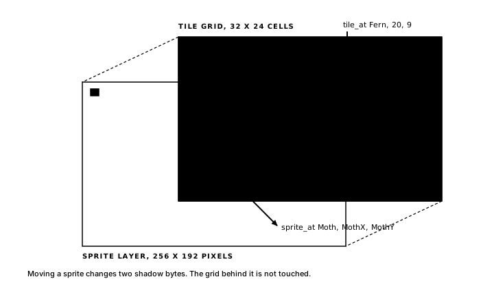
The Z80 reaches the VDP's memory through two ports: control at $BF and data at $BE. Two control-port writes set a VRAM address, and the data port then streams bytes to consecutive addresses: the VDP increments its address pointer after each byte. After the last line of a picture comes the vertical blank before the next refresh. The VDP raises a status-register flag at that point. The profile paces the program on that flag and performs VRAM transfers during the blanking window. Your blocks keep writing plain RAM, exactly as before; the generated library accesses the ports.
Selecting this profile requires one changed line: display tms9918, with the platform line as before. The keypad, the LCD, and text declarations live on the board itself and work the same here; sound cues, shape, and the seven-segment HUD service stay with the 8x8 matrix profile.
Grove
The chapter program is Grove: a white moth over a night garden. Ferns and blooms stand still in the tile grid; the moth is a sprite, steered with 2/4/6/8, one pixel per frame while a key is held.
program Grove

platform tec1g-mon3
display tms9918

sprite Moth color white
  "X..XX..X"
  "XX.XX.XX"
  "XXXXXXXX"
  ".XXXXXX."
  "..XXXX.."
  "...XX..."
  "...XX..."
  "........"
end

tile Fern color lightgreen on black
  "...X...."
  "X..X..X."
  ".X.X.X.."
  "..XXX..."
  "X..X..X."
  ".X.X.X.."
  "..XXX..."
  "...X...."
end

tile Bloom color lightred on black
  "........"
  "..X.X..."
  ".XXXXX.."
  "..XXX..."
  ".XXXXX.."
  "..X.X..."
  "...X...."
  "...X...."
end

state MothX : byte = 124 changed
state MothY : byte = 92  changed
state Init  : byte = 0   changed

pulse Up
pulse Down
pulse Left
pulse Right

bind key KEY_2 held period 1 -> Up
bind key KEY_8 held period 1 -> Down
bind key KEY_4 held period 1 -> Left
bind key KEY_6 held period 1 -> Right

effect PlantScene
    on Init
begin
    tile_at Fern, 4, 18
    tile_at Fern, 9, 6
    tile_at Fern, 14, 20
    tile_at Fern, 20, 9
    tile_at Fern, 26, 16
    tile_at Bloom, 6, 10
    tile_at Bloom, 16, 4
    tile_at Bloom, 23, 19
end

effect MoveUp
    on Up
    updates MothY
begin
    ld a,(MothY)
    or a
    jr z,_stop      ; at the top edge: stay
    dec a
    ld (MothY),a
_stop:
end

effect MoveDown
    on Down
    updates MothY
begin
    ld a,(MothY)
    cp 184          ; bottom clamp: 192 - sprite height
    jr nc,_stop
    inc a
    ld (MothY),a
_stop:
end

effect MoveLeft
    on Left
    updates MothX
begin
    ld a,(MothX)
    or a
    jr z,_stop      ; at the left edge: stay
    dec a
    ld (MothX),a
_stop:
end

effect MoveRight
    on Right
    updates MothX
begin
    ld a,(MothX)
    cp 248          ; right clamp: 256 - sprite width
    jr nc,_stop
    inc a
    ld (MothX),a
_stop:
end

render PlaceMoth
    on MothX, MothY
begin
    sprite_at Moth, MothX, MothY
end
The middle of the file is Rover with pixel coordinates. The clamps say 248 and 184 now because positions name the sprite's top-left pixel on a 256x192 screen and the pattern is 8 pixels square. Everything genuinely new sits at the two ends: three resource declarations at the top, and two block bodies, PlantScene and PlaceMoth, whose lines mention them.
Sprites and tiles are declarations
A sprite declaration is eight quoted rows of eight characters: X for a lit pixel, . for a transparent one, and the transparency matters, because where the moth's pattern has dots, the garden shows through behind it. color white picks one of the sixteen VDP colours (transparent, black, medgreen, lightgreen, darkblue, lightblue, darkred, cyan, medred, lightred, darkyellow, lightyellow, darkgreen, magenta, gray, white), and the colour applies to the complete sprite. Inside block bodies the same sixteen names exist as VC_* equates, so your assembly talks about colour in the same vocabulary as your declarations.
Declaration order does the numbering: the first sprite in the file is slot 0 and pattern 0, the second is slot 1, and so on, up to 31 sprites in a program. In the generated file the pattern rows become bytes and the name becomes its slot:
GlimSpritePats:
        .db     %10011001
        .db     %11011011
        .db     %11111111
        .db     %01111110
        .db     %00111100
        .db     %00011000
        .db     %00011000
        .db     %00000000
Moth              .equ 0   ; sprite slot + pattern
The moth is visible in the bytes themselves: each X became a 1, each dot a 0.
A tile carries two colours, foreground on background, and its rows read the same way. Graphics I colours patterns in banks of eight: one colour byte covers patterns 0..7, the next 8..15, and onward through 32 banks. Tiles that share an (fg, bg) pair fill a bank together, and a new pair opens a new bank. Index 0 stays the blank tile that fills every empty cell; it lives in the first pair's bank, so the first pair's background is the screen background. Grove declares black behind both of its pairs, and the garden sits in darkness. The banking also explains the indexes Glimmer generated:
Fern              .equ 1   ; tile index
Bloom             .equ 8   ; tile index
Fern takes the index beside the blank tile in bank 0; Bloom's colour pair is new, so it opens bank 1 at index 8. Six more ferns and seven more blooms would fit in the two banks already open; a sixteenth distinct colour pair would open bank 15, sixteenth of the 32 the colour table holds.
Shadow-table writes
On the 8x8 matrix, renders drew into a framebuffer and the scan turned it into light. Here a render writes two shadow tables: ordinary RAM, laid out to match the VRAM tables the VDP reads. From the generated state storage:
NameShadow:       .ds 768, 0       ; 32x24 name table shadow
NameDirtyRows:    .db 0, 0, 0      ; 24 dirty-row bits
SpriteShadow:     .ds 128, 0       ; 32 x (y, x, pattern, colour)
SpriteDirty:      .db 0
Each shadow has bookkeeping sized to its table: three bytes of NameDirtyRows carry one bit per grid row, and the single SpriteDirty byte covers the complete sprite table.
Three profile routines write the shadows for you, and each declares its register interface in the generated file:
; Put tile A at column D, row E of the name-table shadow and mark
; the row dirty.
.routine in A,D,E clobbers A,BC,DE,HL,carry,zero,sign,parity,halfCarry
NamePut:NamePut: A = tile index, D = column, E = row. Stores the shadow cell and marks the row's dirty bit.SpriteSet: A = slot, D = x, E = y. Positions a sprite and setsSpriteDirty.SpriteInit: A = slot, D = pattern number, E = colour. Gives a slot its look; the generated startup calls it once per sprite.
For the two common calls, Glimmer generates a pair of assembler ops, keeping the block body concise:
op sprite_at(slot imm8, xcell imm16, ycell imm16)
        ld      a,(xcell)
        ld      d,a
        ld      a,(ycell)
        ld      e,a
        ld      a,slot
        call    SpriteSet
end

op tile_at(tile imm8, col imm8, row imm8)
        ld      a,tile
        ld      d,col
        ld      e,row
        call    NamePut
end
An op expands inline where it is written, so sprite_at Moth, MothX, MothY in PlaceMoth becomes those six instructions: read the two cells into D and E, load the slot, call SpriteSet. tile_at takes immediate coordinates, which suits placing a scene. When a column or row arrives in a register at runtime, the block loads A, D, and E and calls NamePut directly.
The commit-shaped loop
The loop in Grove's generated grove.main.asm begins:
; --- runtime loop ---
Start:
        call    VdpInit
        call    LoadResourcesVram
MainLoop:
        call    VdpWaitVBlank        ; pace on the status-register flag
        call    GlimCommit           ; flush shadows in the blank window
        call    GlimPollBindings
        call    GlimRunLogicEffects
        call    GlimMergeRaised
        call    GlimRunRenderEffects
        call    GlimEndFrame
        jp      MainLoop
From GlimPollBindings down, this is the familiar reactive frame. On the 8x8 matrix, ScanFrame produced the picture; here, VdpWaitVBlank waits for one. The routine polls the status register until the vblank flag comes up (reading the register clears it, arming the next frame), so the program takes exactly one trip around MainLoop per VDP refresh.
GlimCommit then uses the blank window to move the previous frame's shadow writes into VRAM: the complete sprite table if SpriteDirty is set, and each name-table row whose dirty bit is marked. Only after the shadows are flushed does the frame poll keys and run your phases, whose renders write the shadows anew.
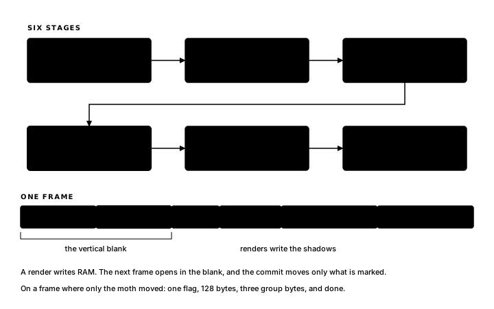
During one frame with key 6 held, the poll fires Right; MoveRight steps MothX; render is a later phase, so the change arrives the same frame, PlaceMoth runs, and sprite_at writes the new x into SpriteShadow and sets SpriteDirty. The screen still shows the old position. The next frame opens in the blank: GlimCommit streams the sprite shadow to VRAM, and the moth stands one pixel to the right. Every shadow write reaches the screen at the top of the following frame, tiles and sprites alike.
A scene planted once
PlantScene runs exactly once because Init is a byte declared changed, so its flag is up before the first frame; the effect fires on frame 1, places eight tiles, and Init holds that one change for the rest of the run. The block's writes land in the name shadow, which the profile tracks with separate dirty row bits, so the header needs no updates line.
Those eight tile_at lines touch eight different grid rows, so frame 1 ends with eight dirty bits standing, and frame 2's commit streams eight rows into VRAM. The VDP then refreshes the garden from VRAM on each picture. The difference: an 8x8 matrix render repaints its layer whenever a fact changes; a VDP program writes each cell once and writes again only what differs.
MothX and MothY carry changed for the same reason Init does: on frame 1, PlaceMoth puts the moth into the sprite shadow alongside the garden, and the first picture contains both.
When a program has cards, an enter block can perform scene placement. Grove has one screen, so a changed cell provides the run-once trigger.
Inside the generated file
Two generated routines implement the profile behaviour. The sprite half of the commit has four steps:
; --- commit: flush dirty shadows to VRAM ---
.routine clobbers A,BC,DE,HL,carry,zero,sign,parity,halfCarry
GlimCommit:
        ld      a,(SpriteDirty)
        or      a
        jr      z,_names
        xor     a
        ld      (SpriteDirty),a
        ld      hl,VRAM_SPRITE_ATTR
        call    VdpSetAddrWrite
        ld      hl,SpriteShadow
        ld      bc,128
        call    VdpWriteBlock
One flag guards one stream: when any sprite moved, all 128 bytes are sent. The 768-byte name table instead uses row-level individual bits. The rest of the routine is the dirty-row loop:
_names:
        ld      d,0                  ; D = dirty-row group 0..2
        ld      b,d                  ; B is dead here; defined only so AZM 0.3
                                     ; stale-register analysis accepts the push bc
                                     ; save/restore below (only C is live)
_group:
        ld      hl,NameDirtyRows
        ld      a,l
        add     a,d
        ld      l,a
        ld      a,h
        adc     a,0
        ld      h,a
        ld      a,(hl)
        or      a
        jr      z,_next
        ld      (hl),0               ; consume the group
        ld      c,a                  ; C = dirty bits, rows D*8 .. D*8+7
        ld      e,0                  ; E = bit within the group
_bits:
        srl     c
        jr      nc,_nbit
        push    de
        push    bc
        ld      a,d
        add     a,a
        add     a,a
        add     a,a
        add     a,e                  ; row = group*8 + bit
        call    CommitNameRow
        pop     bc
        pop     de
_nbit:
        inc     e
        ld      a,e
        cp      8
        jr      c,_bits
_next:
        inc     d
        ld      a,d
        cp      3
        jr      c,_group
        ret
D walks the three group bytes, eight rows to a byte. A zero group byte costs one read and moves on; a marked one is consumed on the spot with ld (hl),0, and srl c shifts its bits out one at a time. Each bit that falls into carry names a row (group times eight plus bit), and CommitNameRow turns the row number into row*32, points the VDP at VRAM_NAME plus that offset, and streams 32 shadow bytes through the data port. On a Grove frame where only the moth moved, the commit reads one flag, sends 128 bytes, reads three group bytes, and is done.
The second routine is the one-time upload that Start calls before the loop begins:
; Upload sprite/tile patterns and the colour groups; assign each
; sprite slot's pattern and colour in the shadow. Called once from
; the loop init, after VdpInit.
.routine clobbers A,BC,DE,HL,carry,zero,sign,parity,halfCarry
LoadResourcesVram:
        ld      hl,VRAM_SPRITE_PAT
        call    VdpSetAddrWrite
        ld      hl,GlimSpritePats
        ld      bc,8
        call    VdpWriteBlock
        ld      a,0                  ; Moth
        ld      d,0
        ld      e,VC_WHITE
        call    SpriteInit
        ld      hl,VRAM_PATTERN + 8   ; Fern
        call    VdpSetAddrWrite
        ld      hl,GlimTilePats + 0
        ld      bc,8
        call    VdpWriteBlock
        ld      hl,VRAM_PATTERN + 64   ; Bloom
        call    VdpSetAddrWrite
        ld      hl,GlimTilePats + 8
        ld      bc,8
        call    VdpWriteBlock
        ld      hl,VRAM_COLOR + 0
        call    VdpSetAddrWrite
        ld      a,VC_LIGHTGREEN * 16 + VC_BLACK
        out     (VDP_DATA),a
        ld      hl,VRAM_COLOR + 1
        call    VdpSetAddrWrite
        ld      a,VC_LIGHTRED * 16 + VC_BLACK
        out     (VDP_DATA),a
        ret
The moth's eight pattern bytes stream to the sprite-pattern area, and SpriteInit records slot 0's pattern and colour in the shadow. Each tile's eight bytes land at VRAM_PATTERN plus index times eight (Fern at +8 for index 1, Bloom at +64 for index 8), and each colour bank gets its single byte, foreground times sixteen plus background.
Before any of this runs, VdpInit programs the VDP's eight registers from a small table, clears the pattern and name tables, and hides all 32 sprites by writing $D1 into every shadow y. That value does two jobs: a sprite whose y is $D1 is off-screen, and the VDP stops processing sprites at the first slot holding it. Declaration order keeps your live sprites contiguous from slot 0, so the terminator always sits right after them.
The next chapter builds a complete game with the profile, including sprite collision, scoring on the tile grid, and cards on the VDP: Building Rushlight.
Exercise
From state to screen. MoveRight changes MothX from 124 to 125 during frame N. When does the VDP first show x=125, and what happens to the value between the state write and the visible picture?