The 8x8 Matrix Profile
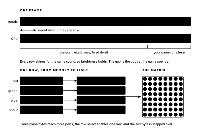
The 8x8 display is eight rows of eight RGB LEDs, and the hardware can light exactly one row at a time. Three ports carry a row's red, green and blue column data; a fourth selects the row that shows it. The Z80 itself sweeps those rows. It paints row 0, holds it lit a moment, paints row 1, and so on around the board, and if it sweeps all eight quickly enough, over and over, your eye fuses them into a steady picture. If it ever stops sweeping, the 8x8 matrix goes dark. The CPU is the display.
Every program you have written in this book has therefore been doing two jobs at once. One is the game. The other is the generated display controller, which shows the current picture every frame. This chapter examines the generated machinery: the scan that keeps the 8x8 matrix lit, the loop shape it forces on the frame, the 32 bytes of memory your renders have been writing all along, and the library routines that write them.
The chapter's program is Compass. While GO is held, a dot runs clockwise around the rim of the 8x8, coloured by the quadrant it is crossing: red along the top, green down the right side, blue along the bottom, yellow climbing the left (north, east, south, west). Releasing GO leaves the dot where it is. One possible design stores the dot's x, y and colour as facts, then has the movement rule update all three. Those redundant cells could become inconsistent if a later rule updates only some of them. Compass stores one byte, a position on the rim, and derives the screen coordinates and colour from it. Whenever the position changes, one compute block refreshes all three derived values together.
Compass
The complete program:
program Compass

platform tec1g-mon3
display matrix8x8

state Position : byte = 0 changed

state DotX   : byte
state DotY   : byte
state Colour : byte

pulse Step

bind key KEY_GO held period 4 -> Step

effect Advance
    on Step
    updates Position
begin
    ld a,(Position)
    inc a
    cp 28
    jr c,_store     ; 27 wraps to 0
    xor a
_store:
    ld (Position),a
end

compute PlaceDot
    on Position
    updates DotX, DotY, Colour
begin
    ld a,(Position)
    cp 7
    jr c,_north
    cp 14
    jr c,_east
    cp 21
    jr c,_south
_west:              ; 21..27: left edge, climbing
    ld b,a
    ld a,28
    sub b           ; y = 28 - Position
    ld (DotY),a
    xor a
    ld (DotX),a
    ld a,COLOR_YELLOW
    jr _colour
_north:             ; 0..6: top edge, heading right
    ld (DotX),a     ; x = Position
    xor a
    ld (DotY),a
    ld a,COLOR_RED
    jr _colour
_east:              ; 7..13: right edge, heading down
    sub 7
    ld (DotY),a     ; y = Position - 7
    ld a,7
    ld (DotX),a
    ld a,COLOR_GREEN
    jr _colour
_south:             ; 14..20: bottom edge, heading left
    ld b,a
    ld a,21
    sub b           ; x = 21 - Position
    ld (DotX),a
    ld a,7
    ld (DotY),a
    ld a,COLOR_BLUE
_colour:
    ld (Colour),a
end

render DrawDot
    on DotX, DotY, Colour
begin
    call FbClear
    ld a,(DotX)
    ld b,a
    ld a,(DotY)
    ld c,a
    ld a,(Colour)
    call FbPlot
end
The rim of the 8x8 matrix is 28 pixels, and Position numbers them 0 to 27, clockwise from the top-left corner. Advance is small: step forward, and past 27 wrap to 0. Held GO fires Step every 4 frames, so the dot orbits for as long as the key stays down.
Position is the fact used by the game rules; drawing takes an x, a y and a colour; the compute derives all three in one place. A threshold ladder splits the rim into its quadrants: positions 0 to 6 lie on the top edge, 7 to 13 on the right, 14 to 20 on the bottom, 21 to 27 on the left. In sequence, the arms show the dot going round: the top edge counts x upward, the bottom edge counts it back down, and the sides do the same with y. Every arm leaves its quadrant's colour in A and falls into the shared store at _colour.
The header line updates DotX, DotY, Colour declares all three products, and DrawDot depends on all three. Storing one fact and deriving the rest means those three cells change together, because one block writes them together, so the render always reads a settled trio.
Advance sits in the logic phase, and its consumer PlaceDot is a compute, an earlier phase, already finished for this frame. So the change to Position defers: the wrapper after Advance's body stages it in Next0, and the dot you see moves on the frame after the pulse. The lap arithmetic gives the game's tempo: 28 steps at 4 frames each is 112 frames a lap. Halving the period halves the lap.
In a running build, holding GO sends the dot along the top in red and changes its colour at every corner. Releasing GO leaves it in place with the colour of its quadrant.
The scan-shaped loop
Every program in this book has opened with the same two lines:
platform tec1g-mon3
display matrix8x8
They select the program's profile: everything the generated file contains beyond the program declarations. The port addresses, the MON-3 key codes, the polling routine, the shape of the runtime loop, and the library at the bottom of the file all come from this one choice. platform names the board and monitor, which is where KEY_GO and the _scanKeys polling come from. display names the output device, and determines the loop structure, because the CPU lights the pixels. The tms9918 display instead builds a loop around a video chip while leaving the reactive core (state, flags, dispatch, rollover) unchanged.
The generated matrix8x8 runtime, from compass.main.asm:
; --- runtime loop ---
Start:
        call    FbClear
        call    HudBlankDig
MainLoop:
        call    ScanFrame            ; show one full frame, then blank
        call    GlimPollBindings     ; game work runs in the blank window
        call    GlimRunDeriveEffects
        call    GlimMergeRaised
        call    GlimRunLogicEffects
        call    GlimMergeRaised
        call    GlimRunRenderEffects
        call    GlimEndFrame
        jp      MainLoop
At Start the profile clears its canvas and display once; then the loop begins. ScanFrame runs first, with the CPU performing one complete pass over the 8x8 matrix, all eight rows, each lit for a fixed dwell, returning with the board dark. Everything else (polling, your three phases, the rollover) runs in that blank window. Your renders write memory in the dark, and the next scan presents their combined result. The player therefore sees the completed framebuffer from the previous blank window.
Each row shines for the same count on every frame, whatever the game did that frame, so brightness stays even across the rows of any one sweep. The dark gap between sweeps is where your game runs, and it is a budget: a longer gap means fewer sweeps a second, and the LEDs are lit for a smaller share of the time. The few dozen instructions executed by this book's blocks per frame change that share by amounts too small to see. Heavy work that fills the blank window dims the display, and that is the first symptom you will notice. And since the scan is by far the frame's largest cost, it paces the frame and makes the frame a useful unit of game time.
The framebuffer
ScanFrame reads its picture from one place, and you have been writing to it since your first render. In the state storage, directly after your facts, the profile reserves it:
; --- state storage ---
Position:         .db 0
DotX:             .db 0
DotY:             .db 0
Colour:           .db 0
Step:             .db 0
Glim_HeldKey:     .db $FF
Glim_HeldCount:   .db 0
Changed0:         .db %00000001   ; flags dispatch tests
Raised0:          .db 0   ; raises for later phases this frame
Next0:            .db 0   ; raises deferred to next frame
Framebuffer:      .ds 32           ; 8 rows x R,G,B,aux
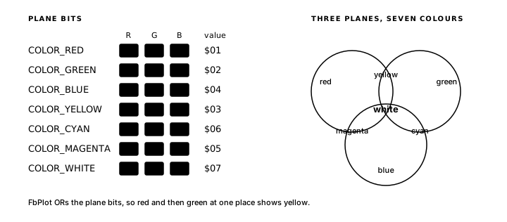
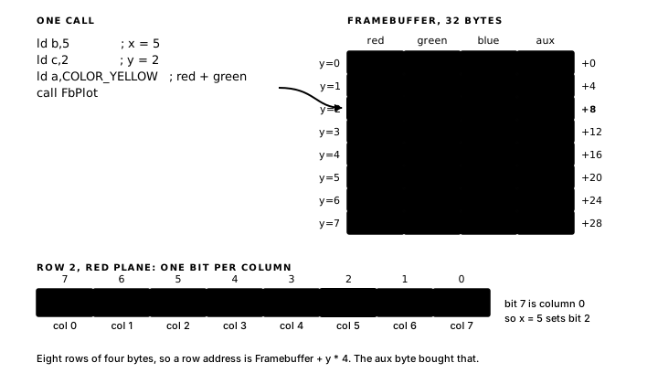
Thirty-two bytes hold the complete picture: eight rows of four bytes (red, green, blue and a fourth, aux, that the scanner steps over). Each of the three plane bytes carries one bit per column. A pixel is one column bit, present in up to three planes: set it in the red byte alone and the pixel glows red; set it in red and green both and the pixel glows yellow. The seven visible colours are the seven ways to occupy one, two, or three planes, and the profile's constants spell that out:
COLOR_RED         .equ $01
COLOR_GREEN       .equ $02
COLOR_BLUE        .equ $04
COLOR_YELLOW      .equ COLOR_RED + COLOR_GREEN
COLOR_CYAN        .equ COLOR_GREEN + COLOR_BLUE
COLOR_MAGENTA     .equ COLOR_RED + COLOR_BLUE
COLOR_WHITE       .equ $07
The A value passed to FbPlot is therefore a set of plane bits.
FbPlot turns x, y and colour into plane-byte writes. Its head, from the profile library:
; Set one pixel. B = x (0-7), C = y (0-7), A = colour bits
; (COLOR_RED/GREEN/BLUE, OR-combined). ORs into the framebuffer.
.routine in A,B,C clobbers A,B,DE,HL,carry,zero,sign,parity,halfCarry
FbPlot:
        ld      d,a                  ; D = colour bits
        ld      a,c
        add     a,a
        add     a,a                  ; y * 4
        ld      e,a
        ld      a,b
        call    MxMask               ; A = pixel mask
        ld      b,a
At four bytes a row, the row's address is Framebuffer + y * 4, and multiplying by four is two add a,a instructions. The padding byte makes that address calculation faster. The rest of the routine shifts the colour bits out of D one at a time, ORing the pixel mask into each plane byte whose bit is set. ORing means FbPlot adds light: plot red and then green at the same coordinates and that pixel shows yellow. A clean picture starts from FbClear, which zeroes the 32 bytes, the call that has opened every redrawing render in this book.
The .routine line above the label is the register interface. It is declared in the generated file and checked on every build: FbPlot consumes A, B and C, and clobbers A, B, DE and HL. DrawBar kept its loop counter in B, a clobbered register, which is why it pushed BC around the call. When a block of yours misuses a library routine's registers, the build fails with the contract, and these lines are where you read what the contract says.
FbPlot calls the small MxMask helper:
; Convert x (0-7, 0 = leftmost) to the matrix bit convention.
.routine in A out A clobbers B,carry,zero,sign,parity,halfCarry
MxMask:
        or      a
        ld      b,a
        ld      a,%10000000
        ret     z
_loop:
        srl     a
        djnz    _loop
        ret
x 0 is the leftmost column and bit 7 of the plane byte, a convention with a purpose: a binary literal in your source reads left to right like the 8x8 itself. Blocks can call MxMask too, when a render builds complete row masks instead of plotting pixel by pixel. Any fact you can turn into an x, a y and three colour bits, you can draw.
ScanFrame, top to bottom
The scanner, the routine that is your display, is twenty-nine instructions. The four ports it drives are equates from the top of the generated file: PortRow at $05 selects the row, and PortRed, PortGreen and PortBlue at $06, $F8, and $F9 take the plane bytes. The complete routine from the profile library:
; Scan all 8 rows with equal dwell, then blank the matrix for game
; work. Excessive work lengthens the dark gap and can reduce brightness.
; Sound and the seven-segment HUD are serviced once per row (8 ticks per frame).
.routine clobbers A,BC,DE,HL,carry,zero,sign,parity,halfCarry
ScanFrame:
        ld      hl,Framebuffer
        ld      c,%00000001          ; row select mask
_row:
        xor     a
        out     (PortRow),a          ; blank before changing colour data
        ld      a,(hl)
        out     (PortRed),a
        inc     hl
        ld      a,(hl)
        out     (PortGreen),a
        inc     hl
        ld      a,(hl)
        out     (PortBlue),a
        inc     hl
        inc     hl                   ; skip aux byte
        ld      a,c
        out     (PortRow),a          ; enable row
        push    bc
        push    hl
        call    SndService
        call    HudScanDig
        pop     hl
        pop     bc
        ld      b,ScanDwellPeriod
_dwell:
        djnz    _dwell
        rlc     c
        jr      nc,_row      ; carry after 8th rotate
        xor     a
        out     (PortRow),a          ; matrix blank on return
        ret
C holds the row select as a one-hot mask, %00000001 for row 0. Each pass around _row blanks the board, writes the row's three plane bytes to the colour ports, steps past the aux byte, and switches the row on. rlc c slides the select bit up one row; after the eighth rotate the bit falls into carry, the loop exits, and a final blank leaves the 8x8 matrix dark for the game work to come.
The colour ports feed whichever row is enabled, so the previous row must go dark before its data changes. Without that blank, each row would briefly show its neighbour's colours on every frame. The dwell follows: djnz spinning B down from ScanDwellPeriod, 255, the wait that sets how long a row shines and, eight times over, how long a frame lasts.
In the middle of every pass sit two calls, SndService and HudScanDig, and they are there because the scan is the steadiest thing the program does. Eight beats a frame, evenly spaced, at full speed, so the profile schedules its other board services there: an active sound cue toggles the speaker here, and one seven-segment digit is strobed here per beat. A value written through HudWriteU16 therefore stays lit by the same trick as the 8x8. Sound and display resources build on both services.
A breakpoint on ScanFrame in compass.main.asm stops execution at the start of a frame, making a step-through of one scan pass possible in Debug80.
Compass moves while GO is held and remains in place when GO is released. The next chapter adds a clock so the program moves while the player watches: Time.
Exercise
One yellow pixel. Which framebuffer row and colour-plane bytes change when a yellow pixel is plotted at x=5, y=2, and which bit mask is ORed into them?