The Shape of a Game
A game written entirely by hand is a large program. Glimmer expresses the same game in a smaller source file that is easier to understand, change and debug.
The intended reader can already read assembly and recognise ld a,(hl) and a conditional jump at a glance. In a game, that assembly must also scan the keys, refresh the display, track time and run each operation in the right order on every frame. This supporting work makes up much of a typical game and changes little from one game to the next. The rules specific to the game end up distributed through it.
There is a name for the usual way of arranging all this: imperative. The program is a list of orders (do this, then this, then check that) and making sure every order lands at the right moment, frame after frame, is your job. Reactive programming turns that around. You write down the program's response to each event, and generated code monitors those events. Almost everything an interactive program does is a reaction: a key goes down, so the player moves; a timer runs out, so the block drops; the score changes, so the display updates. A spreadsheet uses the same model when changing one cell recomputes every formula that refers to it.
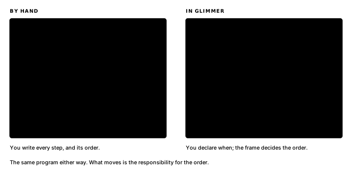
In Glimmer, you declare the facts that store game state, name the moments that trigger work and write the rules and pictures as a few lines of Z80 each, with a label specifying when they run. Glimmer generates the loop, key scanning, timing and change tracking around them, then calls your code for the declared moments.
The language inside every rule is Z80 assembly itself: the real instruction set, the real registers, the real flags. Glimmer emits one ordinary assembly-language source file with your code inside it, which you can open, read and step through to inspect the code generated for any declaration.
Our machine is the TEC-1G, a Z80 single-board computer with a hex keypad and an 8x8 RGB LED matrix (sixty-four pixels, each one mixing red, green and blue). In this chapter we start small: we are going to put one dot on the 8x8 matrix and make it move. I will show you the program in three small steps, and you will run all three yourself in chapter 2, once we have the tools installed.
A dot appears
Here is a complete Glimmer program. It lights one white pixel in the middle of the 8x8 matrix.
program Mover

platform tec1g-mon3
display matrix8x8

state DotX : byte = 3 changed

render DrawDot
    on DotX
begin
    ld a,(DotX)
    ld b,a          ; B = x
    ld c,3          ; C = y, the middle row
    ld a,COLOR_WHITE
    call FbPlot
end
Thirteen lines, and you can already read half of them. The other half becomes clear when we work through it from top to bottom.
program Mover names the program. platform tec1g-mon3 and display matrix8x8 tell Glimmer what hardware we are aiming at: a TEC-1G running the MON-3 monitor, drawing on the 8x8 matrix. These two lines select the keypad wiring, display driver and a small library of drawing helpers. Later examples introduce each of those facilities when they first use it.
state DotX : byte = 3 changedThis is our first fact: a named variable that stores program state. One reading habit will serve throughout the book: Glimmer declarations are built to be read aloud. This one reads: "DotX is a byte, starting at 3, already changed." Every declaration in the language passes that test, and whenever you are unsure what a line means, saying it out loud is the fastest way to find out.
render DrawDot
    on DotX
begin
    ...
end
And here is our first rule (Glimmer calls them blocks). A render block turns memory into light. Its header carries two things: a name and the line on DotX, which specifies when the code runs. This block runs on any frame where DotX changed. Everything between begin and end is real assembly, copied through to the output verbatim.
The generated program advances one frame at a time. Every frame, the generated loop checks which facts changed, runs the blocks that list those facts in an on line, shows the result and begins the next frame. changed marks DotX as already changed before the first frame, so DrawDot runs once at startup and our pixel appears. Without it, the program would keep a dark screen because no change schedules the render. From the second frame on, DotX remains unchanged, so the dispatcher skips DrawDot. Matrix scanning keeps the pixel lit.
DotX is the fact and DrawDot is the render rule. on DotX declares their connection: a change to the fact schedules the rule.
The dot responds
We are making a game, so the next step is to make it respond. A press of key 6 will move the dot right. Here is the program again with that ability added: three new declarations and one new block.
program Mover

platform tec1g-mon3
display matrix8x8

state DotX : byte = 3 changed

pulse Right

bind key KEY_6 rising -> Right

effect MoveRight
    on Right
    updates DotX
begin
    ld a,(DotX)
    cp 7
    jr nc,_stop     ; at the right edge: stay
    inc a
    ld (DotX),a
_stop:
end

render DrawDot
    on DotX
begin
    call FbClear
    ld a,(DotX)
    ld b,a          ; B = x
    ld c,3          ; C = y, the middle row
    ld a,COLOR_WHITE
    call FbPlot
end
Each new declaration depends on the one before it, so their source order also gives the clearest explanation.
pulse RightDotX is a fact that persists across frames. A press of key 6 is a moment: it happens, then ends. Glimmer represents moments with a pulse. A pulse is a fact that holds for exactly one frame before generated code clears it.
bind key KEY_6 rising -> RightThe bind line is the wire from the physical world to your pulse. Following the arrow from left to right gives its meaning: key 6, on a new press, fires Right. The word rising means the pulse fires on the frame the key first goes down: one press, one pulse, however long you hold the key. Movement soon uses a different binding. A rising edge suits discrete actions such as firing, rotating and starting.
effect MoveRight
    on Right
    updates DotX
Throughout this book, a rule is the state change associated with a moment. An effect block contains that rule. Its header declares two relationships: on Right runs the block on any frame where Right fired, and updates DotX marks that fact as changed after the block runs. The body is Z80 again, including the screen boundary: cp 7 keeps the dot at column 7 when it reaches the edge.
DrawDot also calls FbClear because the dot now moves. Each redraw starts from a clean framebuffer and plots the dot where it currently is.
The following diagram traces one press of key 6 through the program, from key to pixel:
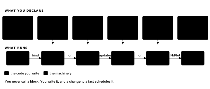
This chain follows the spreadsheet model from the start of the chapter. A formula runs when one of its inputs changes. On the Z80, the same dependency chain appears directly in the declarations: bind ... -> Right, on Right, updates DotX, on DotX.
Each header lists every declared dependency and update: MoveRight declares Right and DotX, DrawDot declares DotX. You can read any one block independently, whether the program has three of them or thirty.
Holding a key down
Crossing the screen with rising takes seven separate presses of key 6. Arcade movement usually continues while the key is held.
By hand, that behaviour is a small state machine run every frame. It keeps a counter, acts when the counter reaches zero, reloads it and resets it on release so the next press fires at once. That final edge is easy to miss.
        call    Key6Down         ; Z if key 6 is down this frame
        jr      nz,_up           ; released
        ld      a,(RepCount)
        or      a
        jr      z,_fire          ; zero: a fresh press, or the wait elapsed
        dec     a
        ld      (RepCount),a
        jr      _done
_fire:
        call    MoveRight
        ld      a,8              ; wait, then repeat
        ld      (RepCount),a
        jr      _done
_up:
        xor     a                ; reset, so the next press fires at once
        ld      (RepCount),a
_done:
That is one key's movement: a byte of storage and a branch you can get subtly wrong. In Glimmer the same behaviour is one line:
bind key KEY_6 held period 8 -> RightA held binding fires on the first press, then fires again every 8 frames for as long as the key stays down. That period controls the movement's feel (drop it to 4 and the dot sprints, raise it to 15 and the dot trudges), and tuning it is editing one digit. Glimmer generates the counter and edge handling; the generated assembly later in this chapter shows the two bytes it uses.
The mirror-image key and rule for leftward travel complete the program:
program Mover

platform tec1g-mon3
display matrix8x8

state DotX : byte = 3 changed

pulse Left
pulse Right

bind key KEY_4 held period 8 -> Left
bind key KEY_6 held period 8 -> Right

effect MoveLeft
    on Left
    updates DotX
begin
    ld a,(DotX)
    or a
    jr z,_stop      ; at the left edge: stay
    dec a
    ld (DotX),a
_stop:
end

effect MoveRight
    on Right
    updates DotX
begin
    ld a,(DotX)
    cp 7
    jr nc,_stop     ; at the right edge: stay
    inc a
    ld (DotX),a
_stop:
end

render DrawDot
    on DotX
begin
    call FbClear
    ld a,(DotX)
    ld b,a          ; B = x
    ld c,3          ; C = y, the middle row
    ld a,COLOR_WHITE
    call FbPlot
end
From the top, the file describes the program as follows: "Mover, on the TEC-1G, drawing on the 8x8 matrix. DotX is a byte, starting at 3, already changed. Two moments, Left and Right. Key 4 held fires Left every 8 frames; key 6 held fires Right. On Left, MoveLeft updates DotX. On Right, MoveRight updates DotX. On DotX, DrawDot." The headers alone tell someone who has never seen a Z80 what this game does. Any single block tells a Z80 programmer everything it touches.
Labels that start with an underscore, like _stop, are local to their block, so each movement rule gets a separate _stop. Blocks end after their last line: Glimmer supplies the return instruction.
The program behind the program
A .glim file is source code, and Glimmer is its compiler, a compiler whose output is assembly language. Mover's compact source becomes a much larger assembly file containing the frame loop, keypad polling, held-key timing, change tracking and your blocks. Here are three excerpts, so you can see which lines came from you and which came from Glimmer.
The generated state storage:
; --- state storage ---
DotX:             .db 3
Left:             .db 0
Right:            .db 0
Glim_HeldKey:     .db $FF
Glim_HeldCount:   .db 0
Changed0:         .db %00000001   ; flags dispatch tests
There is state DotX : byte = 3, a labelled byte holding 3, exactly what you would have written yourself. Each pulse is a byte too, and the two Glim_ cells under them are the held-key repeat clock, generated from the binding. Changed0 stores the change flags in one byte, with one bit per fact. Bit 0, DotX's bit, starts set. The compiler has turned changed in the declaration into that initial 1.
The generated loop:
; --- runtime loop ---
Start:
        call    FbClear
        call    HudBlankDig
MainLoop:
        call    ScanFrame            ; show one full frame, then blank
        call    GlimPollBindings     ; game work runs in the blank window
        call    GlimRunLogicEffects
        call    GlimMergeRaised
        call    GlimRunRenderEffects
        call    GlimEndFrame
        jp      MainLoop
From top to bottom, the loop shows the picture, polls the keys, runs the rules whose facts changed, draws changed output and ends the frame before repeating. Every routine it calls appears further down in the same file.
The generated file also contains your block:
; --- logic block MoveRight ---
.routine
Glim_MoveRight:
    ld a,(DotX)
    cp 7
    jr nc,_stop     ; at the right edge: stay
    inc a
    ld (DotX),a
_stop:
        ld      a,(Raised0)          ; deliver to later phases this frame
        or      CHG_DOTX
        ld      (Raised0),a
        ret
In the middle of that sits your own work: your body, your spacing, your comment, copied in byte for byte, down to the indentation. Around it, Glimmer's wrapping: a label so the dispatcher can call your rule, and after _stop:, three generated instructions that set DotX's change bit. Those instructions compile the line updates DotX: after the block runs, they raise the bit that schedules later blocks with on DotX. The .routine directive above the label enrols the block in the assembler's register-contract checking, which later chapters use as the programs grow.
This file assembles to the bytes the Z80 executes. You can open it, follow it and step through it with a debugger to inspect the exact implementation of a declaration.
For every program in the book, Glimmer generates the frame loop, polling, timing and bookkeeping from the declarations. You write the rules and pictures in Z80, each as a small block with one job and a declared reason to run. The next chapter puts that division into practice by installing the tools and building First Light.
Exercise
The first picture. Mover starts with DotX = 3 changed. Why is the first matrix scan blank, and why does the dot appear on the following scan even though DrawDot runs only once?