Appendix E — TEC-1G Quick Reference
This appendix collects the TEC-1G facts used in Book 1. It is a quick reference for the Debug80 panel and MON-3 profile, not a full hardware manual.
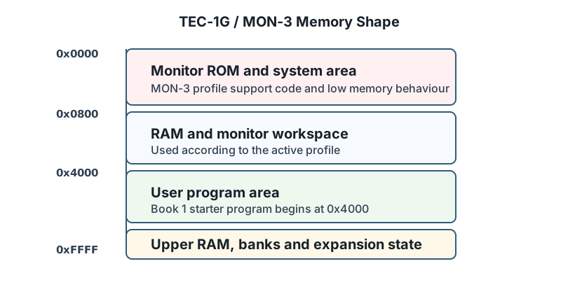
MON-3 Memory Shape
The TEC-1G / MON-3 profile places user code at:
0x4000
The emulator also models monitor ROM, RAM, expansion memory and system-control state. The panel exposes important state through labels such as SHADOW, PROTECT, EXPAND and CAPS.
Panel Sections
| Section | Shows |
|---|---|
| Project | Folder, target, launch options, build state and board transfer. |
| Displays | GLCD, RGB matrix, system LEDs and memory expansion indicators. |
| Machine | LCD, seven-segment display and keypad. |
| Matrix Keyboard | Matrix keyboard mode, modifiers and key grid. |
| Serial | Emulated serial input, output, file send, save and clear. |
| Registers | Z80 register state. |
| Memory | Memory views around registers or an absolute address. |
Serial Settings For Hardware Transfer
Use these CoolTerm settings for the TEC-1 monitor workflow:
4800 baud
8 data bits
No parity
2 stop bits
Add the exact TEC-1G / MON-3 receive-mode sequence after hardware testing or author confirmation.
Common Debugging Clues
If the panel display changes while stepping, the program is writing the corresponding I/O ports.
If the editor highlights ROM source, execution has entered monitor code.
If a memory write appears to vanish, check whether the program is writing a ROM-protected region or whether the visible panel state depends on a banked memory setting.