I/O and Ports
Keyboards send bytes to the CPU, displays receive them and timers report hardware events.
The Z80 handles this through a separate I/O space. In the conventional programming model, devices use an 8-bit port number, giving 256 basic port numbers. The IN and OUT instructions transfer bytes between registers and peripherals over I/O bus cycles. The mapping of port numbers to devices belongs to the target hardware.
The I/O address space
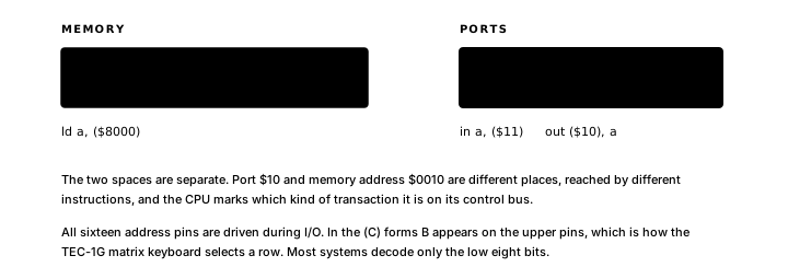
The low byte of an I/O address is an 8-bit port number from 0 to 255. The CPU marks an I/O transaction separately from a memory transaction on its control bus.
The Z80 still drives all sixteen address pins during an I/O transaction. In the (C) forms, C supplies the low 8-bit port number and B appears on the upper address pins. In the immediate (N) forms, N supplies the port number and A appears on the upper pins. Most systems decode only the low eight bits and expose 256 ports. Some hardware also decodes the upper byte. For example, the TEC-1G matrix keyboard uses B to select a row. This upper-byte behaviour is an electrical addressing detail layered on the normal 8-bit port model, so follow the target's hardware documentation when it is used.
The IN and OUT forms in this chapter perform individual byte transfers; the Z80 also has block I/O instructions for repeated transfers.
Writing to a port: OUT
OUT (N), A writes A to the 8-bit port number N:
LD A, $42        ; load value to send
OUT ($10), A     ; write $42 to port $10
The parentheses around $10 mark a port operand, not a memory address. The instruction encodes as two bytes: the OUT opcode and the port number. Only A can supply the data in the immediate form.
OUT (C), R writes register R to the port number in C. Any standard 8-bit register (B, C, D, E, H, L or A) can supply the data:
LD C, $10        ; 8-bit port number
LD D, $42        ; value to send
OUT (C), D       ; write D to port $10
OUT (C), A       ; write A to the same port
Reading from a port: IN
IN A, (N) reads a byte from port N into A:
IN A, ($10) ; read byte from port $10 into AThe immediate form requires A as the destination.
IN R, (C) reads from the port number in C into any standard 8-bit register:
LD C, $10        ; 8-bit port number
IN D, (C)        ; read from port $10 into D
IN A, (C)        ; read from the same port into A
The register-addressed IN R, (C) form sets flags:
- S is set if the byte read has bit 7 set.
- Z is set if the byte read is zero.
- P/V reflects the parity of the byte.
- H and N are reset.
- C (carry) is unaffected.
IN R, (C) sets flags; the immediate form IN A, (N) does not. When code must branch on a value read with the immediate form, a following OR A sets the flags explicitly before the conditional jump.
Polling a port in a loop
Polling repeatedly reads a status port until a condition is met, then accesses the data port.
STATPORT EQU $11
DATAPORT   EQU $10

; READRDY: spin until device is ready, then return the byte read.
; Out: A = received byte
; Clobbers: F
READRDY:
.WAIT:
  IN A, (STATPORT) ; read status into A
  AND $01           ; test bit 0 (ready flag)
  JR Z, .WAIT        ; Z set means bit 0 was 0 - not ready yet; loop
  IN A, (DATAPORT) ; bit 0 is 1 - device is ready; read data into A
  RET
AND $01 keeps only bit 0 and sets Z when that bit was 0. JR Z, .WAIT loops back while Z is set (bit 0 still clear).
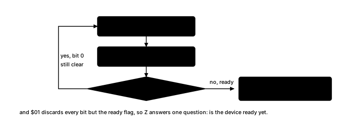
Both reads use immediate low-byte addresses. These examples assume the target decodes only that low byte, as many small Z80 systems do.
Sending a block of bytes
A counted loop can send a sequence of bytes to a fixed port one at a time. HL points to the data and B holds the count:
OUT_PORT EQU $10

; SENDBLK: send B bytes from (HL) to OUT_PORT.
; In:  HL = source address, B = byte count
; Precondition: B > 0
; Clobbers: A, B, HL
SENDBLK:
.SENDLOOP:
  LD A, (HL)       ; load byte at current address
  OUT (OUT_PORT), A
  INC HL           ; advance source pointer
  DJNZ .SENDLOOP   ; decrement B; loop until B reaches 0
  RET
Combining the transfer forms
OUT_PORT EQU $10
IN_PORT  EQU $11

PAYLEN EQU 4

ORG $0000
MAIN:
  LD A, $AA
  OUT (OUT_PORT), A    ; immediate output

  IN A, (IN_PORT)      ; immediate input

  LD C, OUT_PORT
  LD D, $55
  OUT (C), D           ; register-addressed output

  LD HL, PAYLOAD
  LD B, PAYLEN
  CALL SENDBLK
  HALT

ORG $8000
PAYLOAD: DB $10, $20, $30, $40
The first three transfers place their data and port numbers directly in the registers required by each instruction form. The final call applies the SENDBLK routine above: B counts the bytes and HL advances through the source. Its immediate output form leaves B available to DJNZ.
Exercise
Flag behaviour of IN. The comparison should state whether each form updates Z and whether JR Z, IS_ZERO can follow directly:
IN A, (IN_PORT)   ; form A
IN A, (C)         ; form B
The shortest correct sequence for each form may assume C already contains IN_PORT for form B. Tests beginning with Z clear and carry set should use input bytes $00 and $80, recording A, Z and carry after each read and any explicit flag-setting instruction.