Assembly Language
Assembly language gives machine instructions readable names and gives memory addresses labels. The assembler translates that source into the same bytes the CPU executes.
A First Program
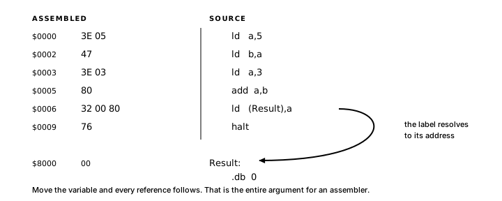
Here is the same add-5-and-3 program from Chapter 2, rewritten in assembly:
ORG $0000
MAIN:
  LD A, 5
  LD B, A
  LD A, 3
  ADD A, B
  LD (RESULT), A
  HALT

ORG $8000
RESULT: DB 0
The six instructions in the body of MAIN are the same six operations you already saw in Chapter 2.
ORG $0000 tells the assembler: everything from here assembles starting at address $0000. MAIN: is a label. The assembler records it as the current address, so MAIN refers to $0000. HALT stops the CPU. ORG $8000 starts a new block at $8000. RESULT: is another label, and DB 0 places one byte with value 0 at the current address, so RESULT refers to $8000.
LD A, 5 loads 5 into A. LD B, A copies A into B. LD A, 3 replaces A with 3. ADD A, B adds B (still 5) to A (now 3), leaving 8 in A.
LD (RESULT), A stores A into the byte named RESULT. The parentheses mean "memory at the address of RESULT."
Instructions and directives
Two constructs in that program are directives to the assembler rather than instructions to the CPU: ORG and DB.
Assembler directives do their work while Atom builds the output. ORG sets an address, EQU gives a constant a name, and DB, DW and DS define storage. Instructions such as LD, ADD and HALT become operations executed by the Z80. Directives do not.
Book 1 is the full language reference. The example below needs only the directives used to place code and reserve named storage.
Labels and placement
A Z80 program still has to respect the memory map from Chapter 1. Code has to land somewhere executable. Variables have to live somewhere writable.
ORG $0000
MAIN:
  ; ... code here ...
  HALT

ORG $8000
COUNT:   DB 0
SCRATCH: DW 0
ORG changes the current output address. The label immediately after it takes that address. In this example MAIN is $0000, COUNT is $8000 and SCRATCH is $8001. DB 0 occupies one byte, so the word after it begins one address later.
Register and immediate loads
LD copies a value from a source to a destination:
LD DESTINATION, SOURCEThe source stays as it was, and the ordinary LD forms leave the flags unchanged. You can copy any of A, B, C, D, E, H and L into any other:
LD A, B     ; A = B
LD D, H     ; D = H
LD L, C     ; L = C
LD A, A     ; legal, pointless
Any 8-bit register takes a one-byte immediate from 0 to 255. A 16-bit register pair takes a two-byte immediate from -32,768 to 65,535; negative values use their two's-complement word representation.
LD A, 42        ; A = 42
LD B, $FF       ; B = 255
LD HL, $8000    ; HL = $8000
LD IX, $4000    ; IX = $4000
Constants
A constant is a name the assembler substitutes for a fixed value:
MAXCOUNT EQU 10
BASEADDR EQU $8000
Wherever you write the name, the assembler substitutes the value. LD A, MAXCOUNT becomes LD A, 10. LD HL, BASEADDR becomes LD HL, $8000. A constant lives entirely at assembly time; its value ends up inside the instructions that use it.
The difference between a constant and a label: a constant is a value you write down (10, $8000). A label is an address the assembler computes from where things end up in the output.
Private labels
A period begins a private label. Its scope runs from the preceding global label to the next global label:
COUNTDOWN:
.LOOP:
  DEC A
  JR NZ,.LOOP
  RET
Another routine may declare its own .LOOP without a collision. Atom associates each private name with its owning global scope. The period is part of the source name and does not count toward the eight significant characters allowed after it.
Named storage
Named storage looks like this:
ORG $8000
COUNT:   DB 0
SCRATCH: DW 0
COUNT starts at $8000. SCRATCH follows immediately at $8001, because COUNT is one byte wide. Since SCRATCH is a word, it occupies $8001 and $8002. If COUNT later becomes a word, every label after it moves and every reference to those labels follows automatically.
DB (define byte) places one byte at the current address. DW (define word) places two bytes in little-endian order. The number that follows is the initial value.
Chapter 4 explains how parentheses select memory and covers the Z80's allowed memory-transfer forms.
Register moves
ORG $0000
MAIN:
  LD A, $FF
  LD B, $10
  LD C, $20
  LD D, A
  LD E, B
  LD HL, $1234
  LD DE, $5678
  LD BC, $0064
  LD D, H
  LD E, L
  HALT
LD A, $FF loads 255 into A (an immediate load, the value encoded directly in the instruction bytes). LD D, A copies A into D, a register-to-register move, no memory involved.
LD HL, $1234 loads a 16-bit immediate into HL: H gets $12, L gets $34. The instruction encodes as three bytes: the opcode, then the value in little-endian order ($34 then $12).
LD DE, $5678 overwrites both D and E. The $FF that was in D from the earlier copy is gone.
The final two instructions, LD D, H and LD E, L, copy HL into DE one byte at a time. After both, DE holds $1234. There is no LD DE, HL instruction. A direct copy using LD takes two 8-bit moves. Chapter 8 shows a stack-based transfer, while EX DE, HL exchanges rather than copies the pairs.
Exercise
Register trace. A trace table should give A, B and C after each instruction and state whether any instruction changes HL.
LD A, $10
LD B, A
LD A, $06
ADD A, B
LD C, A
A complete test program with ORG, MAIN: and HALT allows the final emulator state to be compared with the trace.