Data Tables and Indexed Access
Table-based programs need sequential access for processing every entry and indexed access for reaching one entry directly.
Declaring a byte table
An ORG before a label sets its address, and DB then declares a sequence of byte values:
ORG $8000
SCORES: DB 10, 20, 30, 40, 50, 60
The assembler lays them out in memory in the order listed: $8000 holds 10, $8001 holds 20, $8002 holds 30 and so on.
The name SCORES refers to the address of the first byte in the array, which is the address $8000. It is not the value 10. (SCORES) is the first byte stored there.
Word tables work the same way, with two bytes per entry in little-endian order:
ORG $8010
WIDTHS: DW 100, 200, 300, 400
$8010 and $8011 together hold 100 (low byte $64 at $8010, high byte $00 at $8011).
HL-based sequential access
HL holds an address. LD A, (HL) reads the byte at that address. INC HL advances HL to the next byte.
A DJNZ loop over a byte table looks like this:
LD HL, SCORES      ; HL = address of first entry
LD B, 6            ; B = number of entries
.LOOP_TOP:
  LD A, (HL)       ; A = current entry
  ; ... process A ...
  INC HL           ; advance to next entry
  DJNZ .LOOP_TOP    ; repeat for all entries
The order matters: the body reads the entry first (LD A, (HL)), processes it, then advances (INC HL). An increment before the read would skip the first entry.
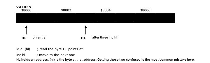
Word entries are two bytes wide, so HL advances by two between them:
LD HL, WIDTHS
LD B, 4
.WORDLOOP:
  LD E, (HL)       ; low byte of current word
  INC HL
  LD D, (HL)       ; high byte of current word
  INC HL           ; now HL points to next word
  ; DE holds current word value
  DJNZ .WORDLOOP
The address vs value distinction
LD HL, SCORES loads the address of the table into HL. HL does not hold 10 (the first element's value).
Only LD A, (HL) produces the value stored in the table.
Labels, variables and code share the same memory
A label that names a variable and a label that marks a point in code are the same kind of thing to the assembler: a memory address, a plain 16-bit number. A load can read from a code address, and a jump can target a data address. In the second case the CPU interprets data bytes as instructions, with results determined by those byte values.
IX-based displaced access
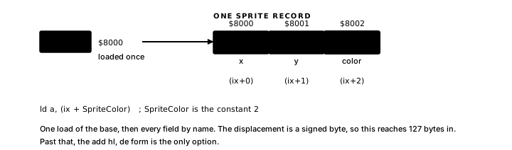
IX is a 16-bit index register. Its specific capability is the (IX+D) addressing mode: D is a signed byte offset, any value from -128 to +127 and LD A, (IX+D) reads the byte at address IX + d while IX keeps pointing where it did.
Once IX holds the base of a record, every field can be named by its offset from that base:
; A three-byte record: offset 0 = id, offset 1 = high byte, offset 2 = low byte
LD IX, RECBASE   ; IX = base of the record
LD A, (IX+0)         ; A = id field
LD B, (IX+1)         ; B = high byte field
LD C, (IX+2)         ; C = low byte field
; IX is unchanged throughout - all three fields read from one base address
The displacement field holds -128 through +127; an offset outside that range is an assembler error.
Accessing a specific table entry by index
Entry N in a byte table is at TABLE + N. Small indices known at assembly time can appear directly as offsets:
LD IX, SCORES        ; IX = base of scores table
LD A, (IX+0)         ; entry 0: value 10
LD A, (IX+3)         ; entry 3: value 40
For a runtime index, the general approach is to add the index to HL:
LD HL, SCORES        ; HL = base
LD DE, 3             ; DE = index (entry 3)
ADD HL, DE           ; HL = scores + 3
LD A, (HL)           ; A = entry 3 = 40
ADD HL, DE adds the 16-bit value in DE to HL, and the load takes whatever is at the result, so an index past the table length reads the bytes that follow the table in memory.
Worked example
TABLELEN EQU 6
RECSIZE  EQU 3

ORG $8000
SCORES:  DB 10, 20, 30, 40, 50, 60
RECORDS: DB $01, $01, $A0
         DB $02, $02, $B0
         DB $03, $03, $C0

ORG $8020
SUM:       DB 0
MAXSCORE: DB 0
REC1_ID:   DB 0
REC1_LO:   DB 0
Section A: sequential HL loop, accumulating a sum.
LD HL, SCORES
LD B, TABLELEN
LD A, 0
.HL_LOOP:
  ADD A, (HL)
  INC HL
  DJNZ .HL_LOOP
LD (SUM), A
HL walks the six score bytes. After six iterations, A = 10 + 20 + 30 + 40 + 50 + 60 = 210 ($D2), which is stored in SUM.
Section B: sequential HL loop, finding the maximum.
LD HL, SCORES
LD B, TABLELEN
LD A, 0
.MAX_LOOP:
  LD C, (HL)
  CP C
  JR NC, .NOMAX
  LD A, C
.NOMAX:
  INC HL
  DJNZ .MAX_LOOP
LD (MAXSCORE), A
A holds the running maximum. The flag-before-branch check shows that CP C is the instruction that sets the flag; JR NC reads it immediately after with nothing in between; carry being clear means A ≥ C, so JR NC skips the update and the running maximum is unchanged. LD A, C runs only when CP C found A less than C, which is a new maximum. After six entries, MAXSCORE holds 60 ($3C).
Section C: IX+d access on a packed record table.
LD IX, RECORDS + RECSIZE    ; IX = base of record 1
LD A, (IX+0)                ; A = id field
LD (REC1_ID), A
LD A, (IX+2)                ; A = lo field
LD (REC1_LO), A
RECORDS + RECSIZE is a compile-time address arithmetic expression: the assembler computes ADDRESS_OF_RECORDS + 3 before emitting any code. IX is loaded with that address in a single LD IX, IMM16 instruction.
The displacement encodes each offset directly, so all three reads work from the single base address in IX. REC1_ID receives $02 (the id byte of record 1) and REC1_LO receives $B0.
Block operations: LDIR and friends
The Z80 has hardware instructions for copying or scanning ranges of memory. LDIR copies BC bytes from the address in HL to the address in DE. After each byte is copied, HL and DE are both incremented and BC is decremented. The instruction repeats until BC reaches zero.
The manual and block-instruction forms for copying four bytes show the difference:
; Without ldir: a manual copy loop
LD HL, SOURCE     ; HL = source address
LD DE, DEST       ; DE = destination address
LD B, 4           ; B = byte count
.COPYLOOP:
  LD A, (HL)      ; A = byte from source
  LD (DE), A      ; write to destination
  INC HL
  INC DE
  DJNZ .COPYLOOP

; With ldir: one instruction
LD HL, SOURCE     ; HL = source address
LD DE, DEST       ; DE = destination address
LD BC, 4          ; BC = 16-bit byte count
LDIR              ; copy 4 bytes, HL and DE advance, BC reaches 0
After LDIR, HL points one byte past the last source byte, DE points one byte past the last destination byte, and BC holds zero.
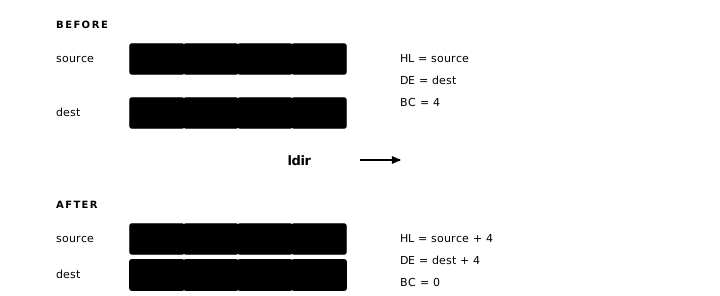
LDIR uses BC as a 16-bit counter. Counts from 1 to 65,535 have their ordinary meaning; an initial BC value of zero wraps on the first decrement and copies 65,536 bytes. The manual loop above uses B as an 8-bit counter and likewise treats an initial zero as 256 iterations.
LDDR copies in the decrementing direction: HL and DE are decremented after each byte rather than incremented. When the destination begins inside the source range at a higher address, starting from the end with LDDR avoids overwriting source bytes before they are read.
CPIR scans memory for a byte value. It reads bytes from (HL), compares each to A, and stops when it finds a match or exhausts BC bytes. After CPIR, Z is set if a match was found, and HL points one past the matching byte. CPDR is the same scan in the decrementing direction.
Atom assembles LDIR, LDDR, CPIR and CPDR directly, like DJNZ.
When both HL and DE are live pointers, as they are during any LDIR sequence, you sometimes need to exchange them. A register-only transfer through A takes six instructions and clobbers A; a stack-based exchange avoids A but touches memory. EX DE, HL does it in one: afterward, DE holds what HL had and HL holds what DE had, while every other register is unchanged.
LD HL, SOURCE
LD DE, DEST
LD BC, 64
LDIR              ; copy 64 bytes; HL and DE now point past the copied region
EX DE, HL         ; HL now points past dest; DE points past source
For element-by-element work on a single table, the DJNZ-over-HL pattern from the first section is usually clearer.
Exercise
Address, value and final pointer. In the chapter example, SCORES begins at $8000 and is followed immediately by RECORDS. The trace should give the values loaded by LD HL, SCORES and LD A, (SCORES), followed by final HL after the six-iteration sum loop. It should also identify the byte a subsequent LD A, (HL) reads and whether that byte belongs to SCORES.