The Computer
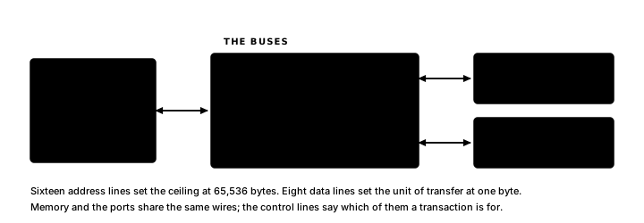
A Z80 computer has three main parts: a CPU, memory and I/O ports. The CPU does the work, fetching instructions and carrying them out. Memory holds the program and the data it works with. I/O ports connect the CPU to the outside world: a keyboard, a display, a storage device, a sensor.
Bits, Bytes and Words
A bit is a single binary digit: 0 or 1. A byte is eight bits: the smallest unit of data the Z80 can read, write or operate on directly. A byte holds values from 0 to 255. Two consecutive bytes form a word, a 16-bit value ranging from 0 to 65,535.
The % prefix marks a binary number: %01110101 is the binary representation of $75 (117 in decimal). The full explanation of binary (how bits combine to make values, two's complement for signed numbers and bit-by-bit arithmetic) is in Numbers, Bits and ASCII.
Hexadecimal
Hexadecimal is base 16. It uses sixteen digits: 0–9 for values 0–9, then A–F for values 10–15. Atom marks hex numbers with a $ prefix. Exactly four bits map to one hex digit, so a byte fits in two hex digits.
| Hex digit | Value | Binary pattern |
|---|---|---|
| 0 | 0 | 0000 |
| 1–9 | 1–9 | 0001–1001 |
| A | 10 | 1010 |
| B | 11 | 1011 |
| C | 12 | 1100 |
| D | 13 | 1101 |
| E | 14 | 1110 |
| F | 15 | 1111 |
So $75 is the byte %0111 0101, a 7 (0111) followed by a 5 (0101). And $FF is %1111 1111, which is 255. A four-digit hex number like $8000 is a 16-bit address. The full conversion tables are in Numbers, Bits and ASCII.
Memory
The Z80 can address 65,536 bytes of memory, arranged as a flat array of 65,536 numbered slots that each hold one byte. The number that identifies a slot is its address.
The full address range runs from $0000 to $FFFF, address zero to address 65,535.
ROM (read-only memory) holds fixed data and keeps its contents when the power goes off. Bootloaders, fixed routines and lookup tables live here. RAM (random-access memory) can be freely read and written, but loses its contents when the power goes off; variables, the stack and anything your program creates or modifies go here.
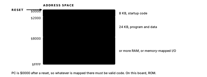
The hardware designer decides which addresses connect to which chips. A system's memory map describes which ranges connect to which hardware. A typical small Z80 board might look like this:
$0000-$1FFF   ROM   (8 KB - startup code)
$2000-$7FFF   RAM   (24 KB - program and data)
$8000-$FFFF   -     (unmapped, or more RAM, or memory-mapped I/O)
At reset, the program counter starts at $0000. That address must contain valid code. On the board above, it is in ROM.
I/O Ports
The Z80 has a separate address space for hardware peripherals, reached with the IN and OUT instructions. In the usual programming model, an 8-bit port number selects the device. The CPU also drives an upper byte on its address pins during I/O; hardware may ignore it or use it for extra selection. Chapter 9 covers that distinction in detail.
The CPU and Its Registers
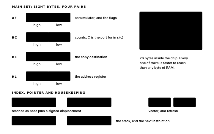
To carry out instructions, the CPU needs fast internal storage: the registers. The Z80 has about 26 bytes of register storage built directly into the chip, much faster than external RAM.
Here is the complete Z80 register set:
| Register | Width | Role |
|---|---|---|
| A | 8 bits | Accumulator. Most arithmetic and logic results end up here. |
| F | 8 bits | Flags. Individual bits record the outcome of the last instruction that affected them. Conditional instructions test them; PUSH AF moves the whole byte. |
| B | 8 bits | General purpose. Frequently used as a loop counter. |
| C | 8 bits | General purpose. Forms the low byte of BC during register-addressed IN/OUT. |
| D | 8 bits | General purpose. |
| E | 8 bits | General purpose. |
| H | 8 bits | General purpose. High byte of HL. |
| L | 8 bits | General purpose. Low byte of HL. |
| BC | 16 bits | B and C as a pair. Used for 16-bit counts and addresses. |
| DE | 16 bits | D and E as a pair. Often used as a destination address when copying data. |
| HL | 16 bits | H and L as a pair. The primary address register — most indirect memory access goes through HL. |
| IX | 16 bits | Index register. Used for indexed memory access (base address + offset). Splits into IXH and IXL. |
| IY | 16 bits | Index register. Same role as IX; a second independent index. Splits into IYH and IYL. |
| SP | 16 bits | Stack pointer. Points to the top of the hardware stack. |
| PC | 16 bits | Program counter. Always holds the address of the next instruction to execute. Jumps, calls and returns are what write to it. |
| I | 8 bits | Interrupt vector register. Used with interrupt mode 2. |
| R | 8 bits | Refresh register. Incremented automatically as each instruction is fetched. |
When B and C are used as the pair BC, B holds the high byte and C holds the low byte, the same pattern as DE (D high, E low) and HL (H high, L low). So if HL = $1A2B, then H = $1A and L = $2B.
The Z80 also has a hidden second copy of A, F, B, C, D, E, H and L called the shadow registers. They are listed in Registers, Flags and Conditions; the chapters use the main register set.
The Fetch-Execute Cycle
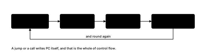
The CPU does one thing, over and over: read the byte at the address in PC, interpret it as an instruction, carry it out and advance PC to the next instruction.
Some instructions are one byte long, some are two, three or four. After executing an instruction, PC advances by exactly as many bytes as that instruction occupied, unless the instruction itself changes PC, which is what jumps and calls do.
Endianness
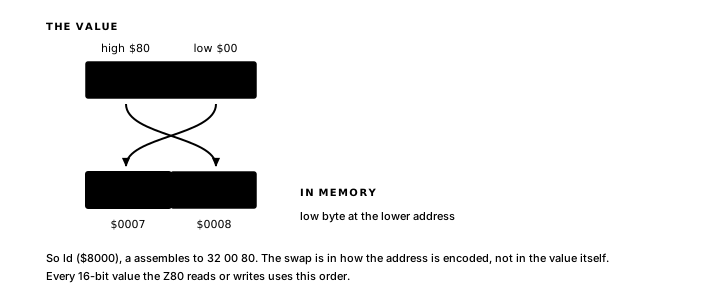
The Z80 is little-endian: the low byte goes at the lower address, the high byte at the higher address.
Storing the word $1A2B at address $8000:
Address   Contents
$8000       $2B    <- low byte first
$8001       $1A    <- high byte second
The same byte order applies when a 16-bit value appears inside an instruction.
Exercise
Parts of the system. A table with one row for each action below should identify the active parts of the computer (CPU, memory or I/O), what travels on the data bus, and what the address selects.
- Fetch the opcode at
$0120. - Read a byte from RAM at
$8004. - Write
$3Cto port$10. - Add B to A.