Flags, Comparisons and Jumps
Z80 instructions record selected outcomes in the flags register. Conditional jumps test those flags to choose the next instruction.
The flags register
F holds eight bits. Each bit is called a flag and records one specific outcome of the last instruction that changed flags. Instructions like SUB, CP, AND, OR, XOR, INC and DEC update them as a side effect.
The LD forms used in these chapters do not touch the flags. INC and DEC update most flags but leave C unchanged. When a JP instruction tests a flag, you need to know which earlier instruction set it and whether anything in between might have changed it.
The four flags you will use most:
| Flag | Name | Set when |
|---|---|---|
| Z | Zero | Result is zero |
| C | Carry | Arithmetic produced a carry out of bit 7, or a borrow in subtraction |
| S | Sign | Bit 7 of the result is 1 |
| P/V | Parity/Overflow | Result parity is even; or signed overflow occurred |
After SUB or CP, Z is set when the two values were equal. After DEC, Z is set when a register reaches zero. After AND, Z is set when every bit the mask selected was 0.
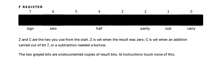
C records unsigned overflow. After addition, C is set when the result exceeded 255, the carry out of bit 7. After SUB or CP, C is set when A was less than the subtracted value: the subtraction had to borrow.
S mirrors bit 7 of the result. In signed arithmetic bit 7 is the sign bit, so S tells you whether the result was negative. When you are working with unsigned values you can usually ignore S.
P/V has two unrelated meanings depending on which instruction set it. After 8-bit arithmetic it reports signed overflow. After logical instructions it reports parity and is set when the result has an even number of 1 bits. Rotate and shift forms differ in whether they update P/V, so the instruction reference is the authority for each one.
For the full flags reference and all condition codes, see Registers, Flags and Conditions.
SUB and CP: subtraction and comparison
SUB N subtracts N from A, writes the result back into A and updates the flags to reflect what happened.
LD A, 8
SUB 3 ; A = 5; Z is clear (result non-zero), C is clear (no borrow)LD A, 3
SUB 5 ; A = $FE (-2); Z is clear, C is set (borrow - A was less than 5)CP N does exactly the same subtraction and sets the same flags, but discards the result.
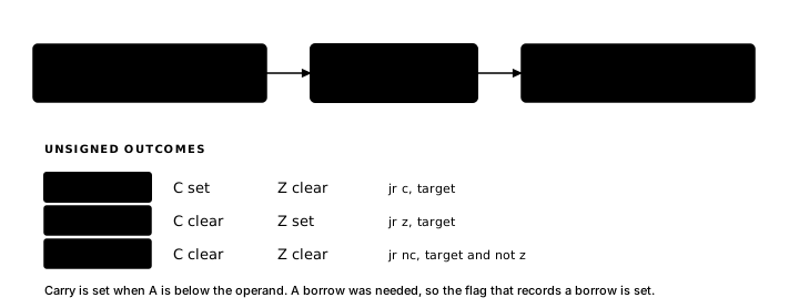
LD A, 5
CP 5 ; subtracts 5; Z is set (result is zero); A stays 5LD A, 3
CP 5 ; subtracts 5; C is set (borrow); A stays 3SUB supplies the computed difference. CP supplies only the relationship (equal, less than, greater than) without changing A.
Logical operations: AND, OR, XOR
AND, OR and XOR each apply a bitwise operation between a mask value and A, store the result back in A, clear C and set Z if the result is zero.
AND N keeps only the bits where the mask has 1, which isolates part of a byte:
LD A, $F3          ; A = %11110011
AND $0F            ; A = %00000011 - upper four bits cleared, lower four kept
OR N sets bits where the mask has 1 and leaves others unchanged:
LD A, $03
OR $80             ; A = %10000011 - bit 7 now set
OR A is a useful special case: A ORed with itself always equals A, so A keeps its value. Only the flags are updated: Z is set if A is zero, C is cleared. CP 0 also tests for zero without changing A, but it produces different flags. CP sets N and clears P/V for this subtraction; OR A clears N and sets P/V according to A's parity.
LD A, 0
OR A       ; Z is set because A is zero

LD A, $FF
OR A       ; Z is clear because A is non-zero
XOR N toggles bits where the mask has 1:
LD A, $FF
XOR $0F            ; A = %11110000 - lower four bits flipped
The common XOR A form XORs A against itself, which always produces zero; every bit cancels. LD A, 0 also zeros A but leaves the flags unchanged.
XOR A ; A = 0; Z is set; C is clearAll three instructions accept a register, an immediate byte, (HL) or an index register form. The quick reference for arithmetic and logical instruction forms is in Addressing, Prefixes and Forms.
JP: moving execution to a new address
Chapter 1 established that the CPU executes the instruction at the address in PC, then advances PC to the next instruction. JP breaks that sequence: it puts a new address into PC, and execution continues from there.
JP $8010 ; PC becomes $8010; next instruction comes from $8010A label normally provides the target instead of a raw address:
JP .DONE
; code written here is never reached
.DONE:
  ...
The assembler works out the address of DONE and encodes it into the instruction bytes.
On its own, an unconditional JP is mostly useful for two things: skipping over a block of code (which becomes the else-half of a conditional structure), or jumping back to an earlier address to repeat something.
Conditional JP: testing the flags
A conditional JP works exactly like an unconditional one, with one addition: before changing PC, it checks a flag. If the flag condition is met, PC changes and execution continues from the target address. If it is not met, execution continues with the instruction that immediately follows: the jump falls through.
JP Z, TARGET checks Z. If Z is set, the jump happens.
JP NZ, TARGET is the inverse: it jumps when Z is clear and falls through when Z is set. The N prefix means "not": NZ is "not zero", NC is "not carry".
The condition codes you will use most:
| Code | Meaning |
|---|---|
Z | Jump if Z is set |
NZ | Jump if Z is clear |
C | Jump if C is set |
NC | Jump if C is clear |
JP also supports M (S set) and P (S clear), which test the sign bit of the preceding result. A general signed less-than or greater-than comparison also has to account for signed overflow, which can flip the meaning of S. The PE and PO conditions test P/V; that flag represents parity after some instructions and signed overflow after others. The full list is in Registers, Flags and Conditions.
A CP or logical instruction sets a flag, after which a conditional JP selects which block runs:
CP 5
JP NZ, .SKIP    ; A != 5: jump to skip
; ... this body runs only when A == 5 ...
.SKIP:
CP 5 subtracts 5 from A and sets Z if the result was zero, that is, if A was 5. JP NZ then jumps if Z is clear, which means A was not 5.
The condition on JP is the condition that causes the jump, not the condition that runs the body.
AND with a single-bit mask lets you test one specific bit of A and act on the result:
LD A, (STATUS)
AND $04            ; keep only bit 2; Z is set if bit 2 was 0
JP Z, .BITCLEAR    ; bit 2 was 0 - go to .BITCLEAR
If bit 2 was 1, the result is non-zero, Z is clear and execution falls through.
The Flag-Before-Branch Check
A conditional jump (
JP CC,JR CC) can be checked in three steps.Step 1: Which instruction set the flag you're testing? The scan starts at the jump and moves backward to the instruction that last modified the flag. Common candidates for Z include
CP,SUB,AND,OR,XOR,INC,DEC,ADD,SBCandIN R,(C). Common candidates for C includeCP,SUB,ADD,ADC,SBC,AND,OR,XOR,RL*andRR*.Step 2: Does anything between that instruction and the jump also touch that flag? The ordinary
LDinstructions used in this book are safe to place between a comparison and a jump.INCandDECupdate most flags but leave C alone. Arithmetic and logical instructions each update their own set of flags. If something in between modifies the flag you are testing, the jump will read the wrong value.Step 3: Is the flag's meaning what you think it is? C means different things after
ADD(carry out of bit 7) versus afterCPorSUB(unsigned borrow, set when A was less than the operand). Z always means "result was zero," but "result" afterCPis the discarded difference, not a stored value.
Short relative jump: JR
JP encodes a full 16-bit target address in its three instruction bytes. JR encodes only a signed 8-bit displacement, measured from the address immediately after the JR instruction. This limits the target to 127 bytes forward or 128 bytes backward from that following address, but the instruction is one byte shorter than JP.
JR NZ, LABEL jumps to LABEL if Z is clear. The conditional forms support Z, NZ, C and NC only, fewer conditions than JP.
JP | JR | |
|---|---|---|
| Address encoding | Full 16-bit address | Signed 8-bit displacement |
| Instruction size | 3 bytes | 2 bytes |
| Reach | Anywhere in 64K | ≈ 128 bytes backward / 127 forward |
| Conditions available | Z, NZ, C, NC, M, P, PE, PO | Z, NZ, C, NC only |
For short loops and nearby tests, JR saves a byte per jump and the range is rarely a problem. For anything that might be far away, or when you need M, P, PE or PO, JP is the safe choice. The assembler will tell you if a JR target is out of range. Jump range limits for JR and the related DJNZ instruction (Chapter 6) are in Registers, Flags and Conditions.
Detecting a negative number: the CP $80 technique
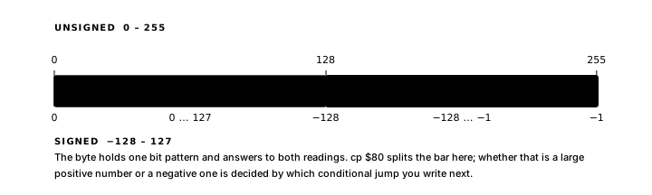
A signed value in A may need conversion to its absolute value. A signed byte stores values from −128 to 127. Negative values have bit 7 set, which means their unsigned interpretation is 128 or greater. You can test which half A falls in by comparing it against 128 as an unsigned value:
  CP $80              ; compare A (unsigned) against 128
  JR C, .NONNEG ; carry set means A < 128 -> non-negative
  NEG                 ; negate A: A = -A
.NONNEG:
  ; A now holds the absolute value
If carry is clear, A is 128 or above, which means bit 7 is set and the value is negative.
This pattern works because signed and unsigned representations share the same bits; the only difference is how you interpret bit 7. If A holds an unsigned value, this test gives the wrong answer, since 128 through 255 are valid positive results in unsigned arithmetic, and CP $80 will treat them all as negative.
NEG applied to −128 gives −128: the mathematical result (+128) does not fit in a signed byte, so the bit pattern ($80) is unchanged.
Tracing a wrong branch
When a conditional jump takes the wrong path, inspect the program in this order:
- Open the Atom listing and confirm that the code, data and jump target are at the expected addresses.
- Step to the instruction that should establish the condition and record its operands and resulting flags.
- Step from there to the jump. If another instruction changes the tested flag, the branch is using that newer result.
Debug80 and other Z80 debuggers show registers, flags and memory after each instruction. Predicting the one value that should change before taking a step makes the first disagreement easy to isolate. The listing and other build artifacts are described in Book 1, Chapter 6.
Exercise
Flag prediction. A result table for each independent sequence should give the final A and whether Z and C are set or clear. The last sequence needs one row after XOR A and another after DEC A.
LD A, 5
CP 5        ; Z = ? C = ?

LD A, 5
CP 6        ; Z = ? C = ?

LD A, 5
CP 3        ; Z = ? C = ?

LD A, 0
XOR A       ; establish Z set and C clear
DEC A       ; Z = ? C = ?
Step mode provides the observed flags for comparison.