Appendix and Useful Links
Ports
| Port | Direction | Description |
|---|---|---|
00H |
In | Keypad press encoder Bit 0-4: HexPad Bit 5: Function Key (active low) Bit 6-7: N/A |
01H |
Out | Seven segment digits switch Bit 0-1: Data segments Bit 2-5: Address segments Bit 6: FTDI Rx (out), Disco LEDs Bit 7: Speaker |
02H |
Out | Seven segment LED switch Bit 0: G segment Bit 1: F segment Bit 2: C segment Bit 3: D segment Bit 4: E segment Bit 5: DP segment Bit 6: B segment Bit 7: A segment |
03H |
In | System input Bit 0: Matrix Keyboard (DIP-3) Bit 1: Protect Mode (DIP-3) Bit 2: Expand Mode (DIP-3) Bit 3: Expand Status Bit 4: Cartridge Flag Bit 5: General Input Bit 6: Keypress Flag Bit 7: FTDI Tx (in) |
04H |
In/Out | LCD Instruction |
05H |
Out | LED 8x8 Matrix Horizontal (TEC Expander) |
06H |
Out | LED 8x8 Matrix Vertical (TEC Expander) |
07H |
Out | Graphical LCD Instruction |
84H |
In/Out | LCD Data |
87H |
Out | Graphical LCD Data |
F8H |
In/Out | Spare (TEC Expander & I/O Bus) |
F9H |
In/Out | Spare (TEC Expander & I/O Bus) |
FAH |
In/Out | Spare (I/O Bus) |
FBH |
In/Out | Spare (General I/O & I/O Bus) |
FCH |
In/Out | RTC (Real Time Clock) (General I/O & I/O Bus) |
FDH |
In/Out | SD (Secure Digital) Flash Card (General I/O) |
FEH |
In | Matrix Keyboard |
FFH |
Out | System Latch Bit 0: Shadow (active low) Bit 1: Protect Bit 2: Expand Bit 3: FF-D3 (Mem Bus) Bit 4: FF-D4 (Mem Bus) Bit 5: FF-D5 (Mem Bus) Bit 6: FF-D6 (Mem Bus) Caps Lock: Matrix Keyboard |
Serial Connection
| Constant | Value |
|---|---|
| FTDI to USB Serial Transmission | 4800-8-N-2Baud 4800, 8 packet bits No parity, 2 stop bits |
The baud rate value can be modified, but the other constants are the same.
Function Key Shortcuts
| Key | Shortcut | Key | Shortcut | Key | Shortcut | Key | Shortcut |
|---|---|---|---|---|---|---|---|
0 |
Quick Links | 1-3 |
Addr. Jump | 4 |
Intel Load | 5 |
GLCD Term |
6 |
Save Session | 7 |
Load Session | 8 |
NOP’s Fill | A |
Restore Blk. |
B |
Backup Blk. | C |
Smart Copy | D |
Diss. View | E |
Expand |
F |
Catalog | AD |
Main Menu | + |
Insert Byte | - |
Delete Byte |
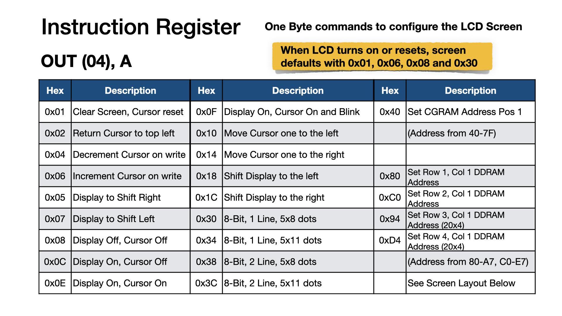
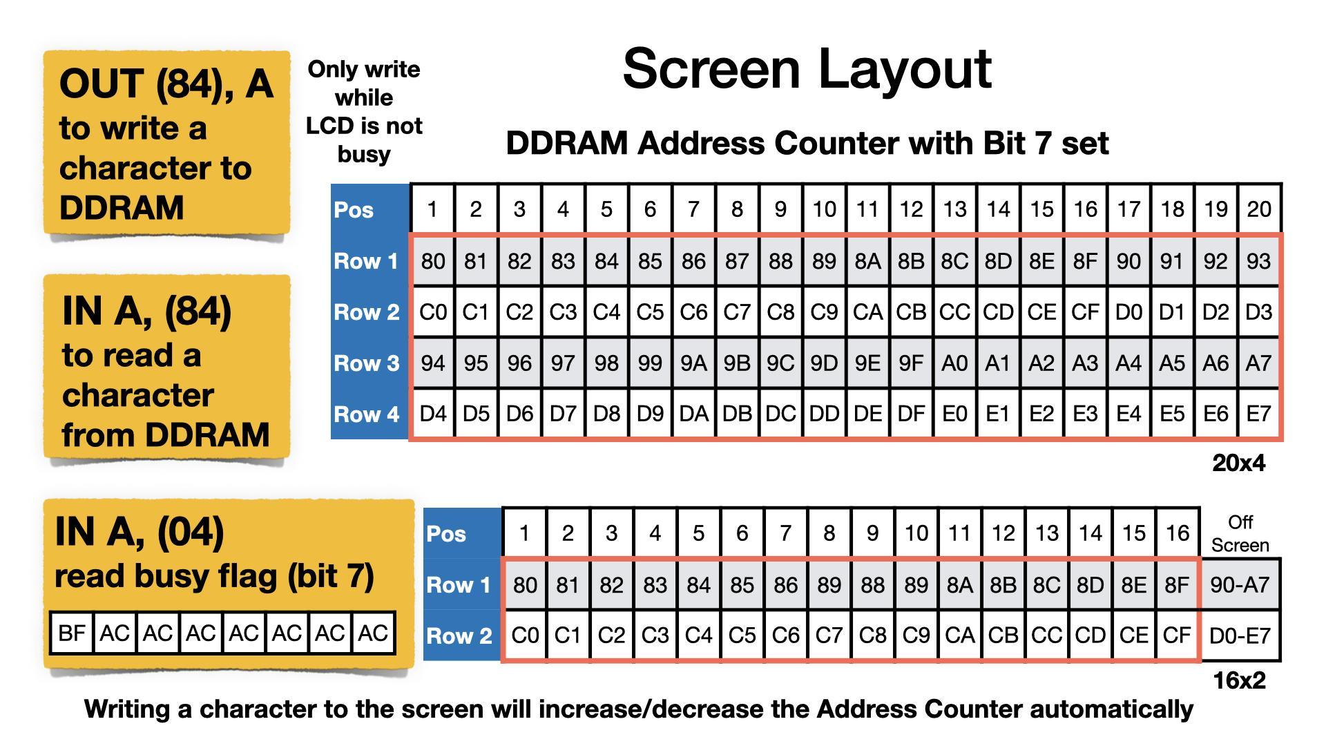
LCD Cheatsheet
Z80 instructions to communicate with the LCD screen are given as direct commands. IE: OUT (04),A. Mon3 also provides API routines that do the same but also check for the LCD busy state. If using direct port instructions, the LCD busy flag is to be checked prior to the instruction call. The example code provided uses the API routines.

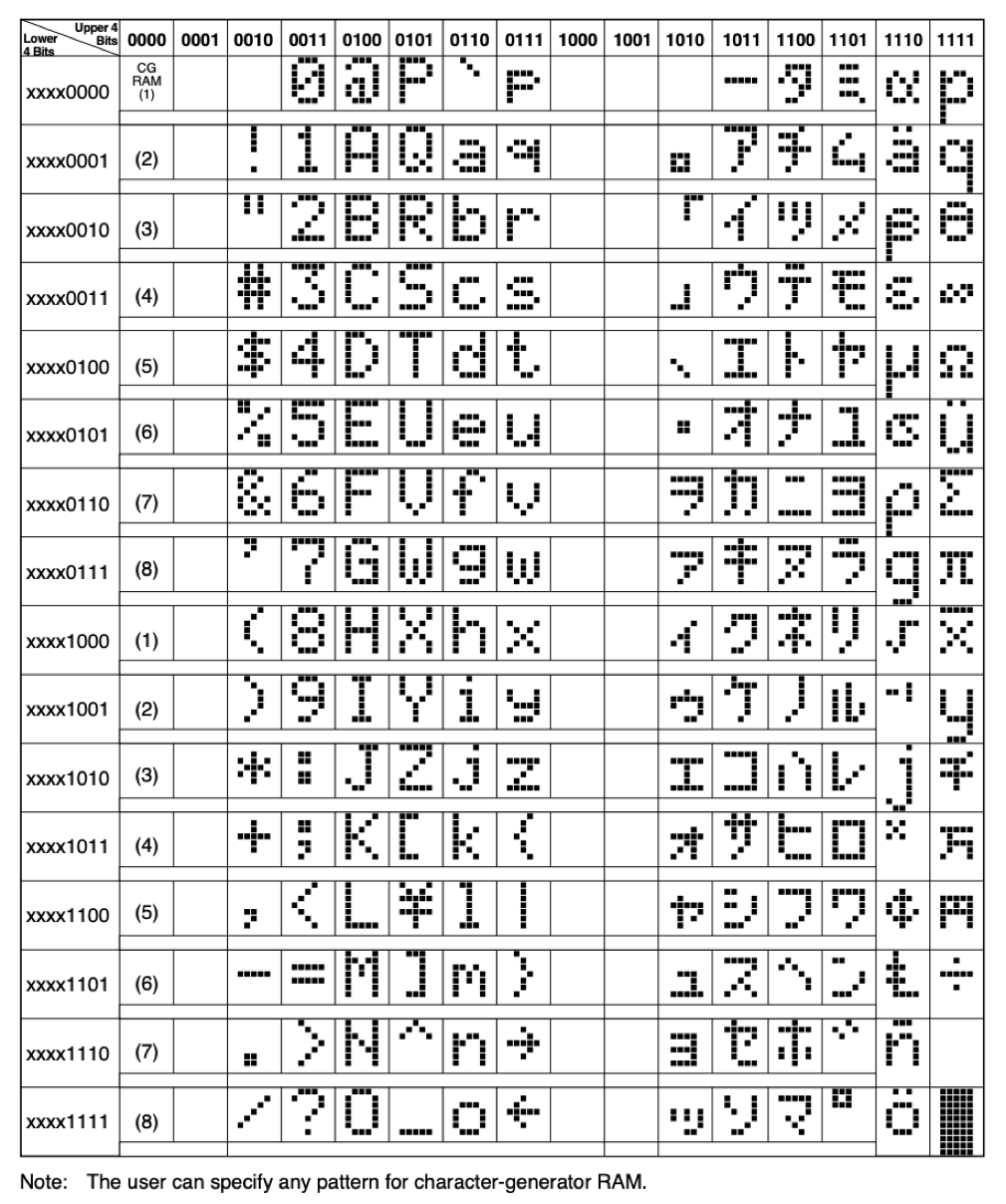
Character Table
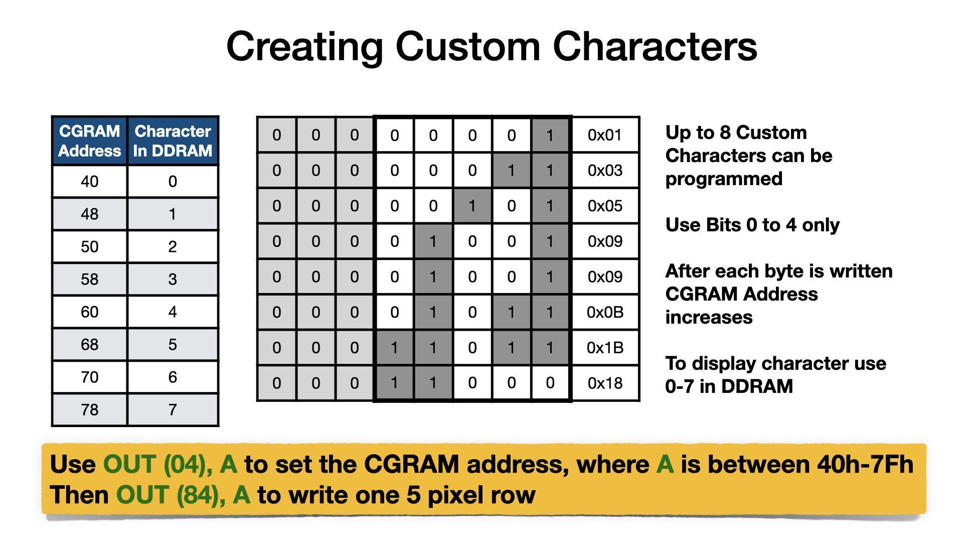
Example Using CGRAM and DDRAM
_stringToLCD   .equ  13
_charToLCD     .equ  14
_commandToLCD  .equ  15

; LCD Setup
4000 0E 0F    ld c,_commandToLCD  ;LCD Instruction API routine
4002 06 01    ld b,01H            ;Clear display
4004 D7       rst 10H             ;call API routine
4005 06 38    ld b,38H            ;8-bit, 2 lines, 5x8 characters
4007 D7       rst 10H             ;call API routine

; Tell the LCD that next data will be to CGRAM
4008 06 40    ld b,40H            ;CGRAM entry
400A D7       rst 10H             ;call API routine

; Save multiple characters to CGRAM using lookup table
400B 06 40    ld b,40H            ;8 characters, 8 bytes each
400D 0E 0E    ld c,_charToLCD     ;LCD Data API routine
400F 21 3F 40 ld hl,403FH         ;LCD custom character table
loop1:
4012 7E       ld a,(hl)           ;get custom character byte
4013 23       inc hl              ;move to next item in table
4014 D7       rst 10H             ;call API routine
4015 10 FB    djnz loop1          ;continue for all 64 char bytes

; Display first line of text
4017 0E 0F    ld c,_commandToLCD  ;LCD Instruction API routine
4019 06 82    ld b,82H            ;move cursor to row 1, col 3
401B D7       rst 10H             ;call API routine
401C 21 34 40 ld hl,4034H         ;ASCII text
401F 0E 0D    ld c,_stringToLCD   ;LCD String API routine
4021 D7       rst 10H             ;call API routine

; Display custom characters
4022 0E 0F    ld c,_commandToLCD  ;LCD Instruction API routine
4024 06 C0    ld b,0C0H           ;move cursor to row 2, col 1
4026 D7       rst 10H             ;call API routine
4027 06 08    ld b,08H            ;8 characters
4029 0E 0E    ld c,_charToLCD     ;LCD Data API routine
loop2:
402B 78       ld a,b              ;set A to current character
402C D7       rst 10H             ;call API routine
402D 3E 20    ld a,20H            ;space character
402F D7       rst 10H             ;call API routine
4030 10 F9    djnz loop2          ;continue for all 8 characters

; All done, wait for key press and exit
4032 CF       rst 08H             ;key wait and press (HALT)
4033 C9       ret                 ;exit
TEXT TABLE:
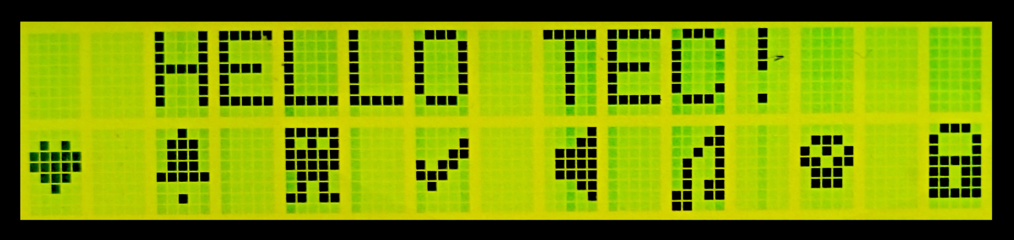
4034 48 45 4C 4C 4F 20 54 45 43 21 00 ; "HELLO TEC!"
CHAR TABLE:
403F 00 0A 1F 1F 0E 04 00 00 ; Heart
4047 04 0E 0E 0E 1F 00 04 00 ; Bell
404F 1F 15 1F 1F 0E 0A 1B 00 ; Alien
4057 00 01 03 16 1C 08 00 00 ; Tick
405F 01 03 0F 0F 0F 03 01 00 ; Speaker
4067 01 03 05 09 09 0B 1B 18 ; Note
406F 00 0E 15 1B 0E 0E 00 00 ; Skull
4077 0E 11 11 1F 1B 1B 1F 00 ; Lock
Useful Links
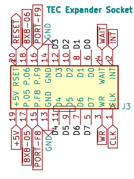
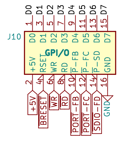
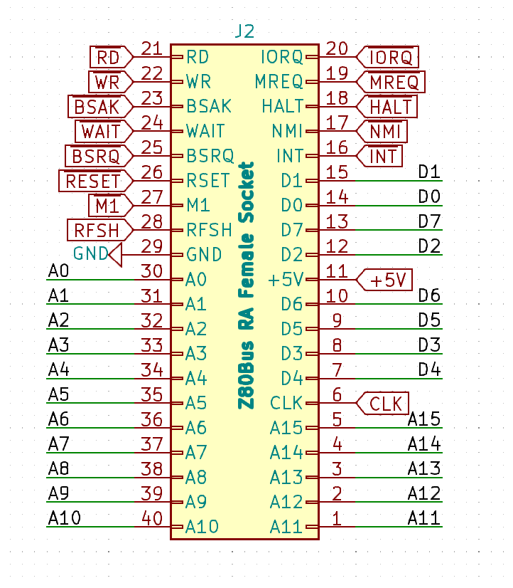
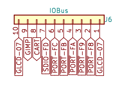
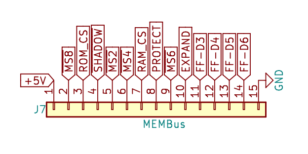
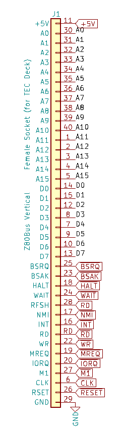
I/O Connectors
The connector diagrams below cover the Expander Socket, General Purpose
I/O, Z80 Bus Connector and TEC Deck Connectors. Note: pin 28 is RD.