Advanced Programming
To assist when developing Z80 programs, Mon3 contains built-in functionality that makes it easy to interface with the TEC-1G hardware.
RST (Restart) commands
RST commands on the Z80 are one-byte call commands that execute code at certain address locations defined by the Z80. The following table outlines the routines.
| Command | Op Code | Description |
|---|---|---|
RST 00H |
C7 |
Software monitor reset. |
RST 08H |
CF |
Key wait and press routine. This simulates a HALT command where the TEC waits for a key to be pressed and then continues execution. If a key is currently being held down, the routine waits until the key is released and then detects the next key. The key that has been pressed is stored in register A.RST 08H waits for a keypress.LD B,A loads the key to register B. |
RST 10H |
D7 |
API entry call. Executes a monitor routine. See the API calls section below for details. |
RST 18H |
DF |
API 2 entry call. Graphical LCD routine entry. See the GLCD section below for details. |
RST 20H |
E7 |
Scan Seven Segments and Keys. Multiplexes the seven-segment displays and checks for a key press. It can be used to display information on the seven segments and check for a key to be pressed. It must be called in a loop until a key is pressed to maintain seven-segment persistence. Returns Zero flag set when a key is pressed and register A with the key value. Register DE points to the seven-segment data. See the first program in the Quick Start Programs chapter for an example. Registers DE, A, and B are modified. |
RST 28H |
EF |
LCD Busy Check. Call before sending a command to the LCD when directly communicating with the LCD. The routine only exits when the LCD Busy flag is not set.RST 28H checks the LCD busy flag.LD A,01H loads A with a clear-screen instruction.OUT (04),A sends the instruction to the LCD. |
RST 30H |
F7 |
Breakpoint entry. Breaks code execution at the current address location. See the Debugging Programs section for details. |
RST 38H |
FF |
Maskable interrupt handler. Jumps here with Interrupts Enabled (EI), Interrupt Mode 1 (IM 1), and when the INT pin on the CPU goes low. Mon3 does nothing when this happens, but a user-defined routine can be used. See the Interrupt section below. |
Interrupts
The Z80 CPU has the ability to interrupt the execution of code, handle the interrupt and then resume code execution. This is done in software with Interrupts Enabled (EI) and Interrupt Mode 1 (IM 1) and by hardware when the INT line on the CPU goes low. Mon3 ignores interrupts, but a user-defined routine can be provided to handle the interrupt. To do this, the address of the interrupt routine is to be placed at RAM address 0892H.
       ei                 ; Enable interrupts
       im 1               ; Interrupt mode 1
       ld hl,myINT          ; Interrupt routine
     ld (0892H),hl          ; Save address in 0892H
       ... continue

myINT:
       ld c,03H   ; Bell routine
       rst 10H    ; Call API
       reti       ; Exit Int routine
This code will sound a bell tone in the speaker when an interrupt occurs.
NMI (Non-Maskable Interrupts)
Non-Maskable Interrupts occur when the NMI line on the CPU goes low. These interrupts will always trigger. Mon3 ignores the NMI line, but a user-defined routine can be provided to handle the interrupt. To do this, the address of the interrupt routine is to be placed at RAM address 0894H.
     ld hl,myNMI            ; NMI routine
     ld (0894H),hl          ; Save address in 0894H
       ... continue

myNMI:
       ld c,03H   ; Bell routine
       rst 10H    ; Call API
       retn       ; Exit NMI routine
This code will sound a bell tone in the speaker when an NMI occurs. The TEC-1G has an NMI jumper that can set NMI to trigger on a Keypad press, a HALT instruction or externally (no jumper).
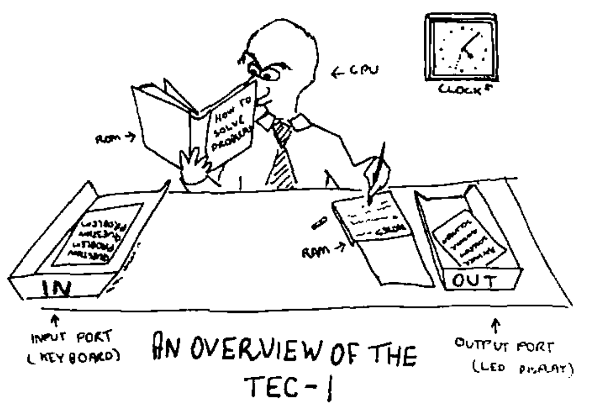
Cartoon credit: Ken Stone, TE Issue 10, 1983.
API (Application Programming Interface) commands
The API on Mon3 exposes routines used by Mon3 which can be used in your own programs. It makes writing code quicker and easier by exposing monitor services through a small call interface.
General conventions
The register C holds the API Call number. All other registers except the IX register can be used as parameters if needed. Executing a RST 10H or D7 calls the API.
General Interface
ld c,[API Call Number]
rst 10H
Some Examples
          ;Produce a short Beep from the speaker
0E 03     ld c,3      ;beep call number
D7        rst 10H

          ;Display the letter 'G' on the LCD Screen
0E 0E     ld c,14     ;charToLCD call number
3E 47     ld a,"G"    ;parameter
D7        rst 10H

          ;Wait for a period of time
0E 21     ld c,33     ;timeDelay call number
21 00 30  ld hl,3000H ;parameter
D7        rst 10H
To assist with API call number references, the file api_includes.z80, in the GitHub repository, contains the API Call Number with its Text equivalent for use with your own code.
See the MON-3 source in the TEC-1G repository.
API Call List
Utility Calls
| Call | # | 0x |
|---|---|---|
softwareID |
0 | 0 |
versionID |
1 | 01 |
preInit |
2 | 02 |
beep |
3 | 03 |
convAToSeg |
4 | 04 |
regAToASCII |
5 | 05 |
ASCIIToSegment |
6 | 06 |
stringCompare |
7 | 07 |
HLToString_ |
8 | 08 |
AToString |
9 | 09 |
scanSegments |
10 | 0A |
displayError |
11 | 0B |
checkStartEnd |
30 | 1E |
Serial Calls
| Call | # | 0x |
|---|---|---|
serialEnable |
20 | 14 |
serialDisable |
21 | 15 |
txByte |
22 | 16 |
rxByte |
23 | 17 |
intexHexLoad |
24 | 18 |
sendToSerial |
25 | 19 |
receiveFromSerial |
26 | 1A |
sendAssembly |
27 | 1B |
sendHex |
28 | 1C |
genDataDump |
29 | 1D |
stringToSerial |
45 | 2D |
System Latch Calls
| Call | # | 0x |
|---|---|---|
getCaps |
37 | 25 |
getShadow |
38 | 26 |
getProtect |
39 | 27 |
getExpand |
40 | 28 |
setCaps |
41 | 29 |
setShadow |
42 | 2A |
setProtect |
43 | 2B |
setExpand |
44 | 2C |
toggleCaps |
48 | 30 |
LCD Calls
| Call | # | 0x |
|---|---|---|
LCDBusy |
12 | 0C |
stringToLCD |
13 | 0D |
charToLCD |
14 | 0E |
commandToLCD |
15 | 0F |
Input Calls
| Call | # | 0x |
|---|---|---|
scanKeys |
16 | 10 |
scanKeysWait |
17 | 11 |
matrixScan |
18 | 12 |
joystickScan |
19 | 13 |
matrixScanASCII |
53 | 35 |
parseMatrixScan |
54 | 36 |
Misc. Calls
| Call | # | 0x |
|---|---|---|
timeDelay |
33 | 21 |
RTCAPI |
46 | 2E |
random |
49 | 31 |
setDisStart |
50 | 32 |
getDisNext |
51 | 33 |
getDisassembly |
52 | 34 |
LCDConfirm |
55 | 37 |
getGLCDTerm |
56 | 38 |
setGLCDTerm |
57 | 39 |
loadFromDisk |
58 | 3A |
openFile |
59 | 3B |
readSector |
60 | 3C |
writeSector |
61 | 3D |
RGBScan |
62 | 3E |
Menu Calls
| Call | # | 0x |
|---|---|---|
menuDriver |
31 | 1F |
paramDriver |
32 | 20 |
menuPop |
47 | 2F |
Sound Calls
| Call | # | 0x |
|---|---|---|
playNote |
34 | 22 |
playTune |
35 | 23 |
playTuneMenu |
36 | 24 |
API Utility Calls
softwareID #0 (00H)
Get Software ID String
- Input: nothing
- Return: HL = Pointer to SOFTWARE ASCII String
- Destroy: none
versionID #1 (01H)
Get Version Number and Version String
- Input: nothing
- Return:
HL= pointer to release ASCII string - Return:
BC= release major version number - Return:
DE= release minor version number - Destroys: none
preInit #2 (02H)
Performs a cold reset as if the TEC-1G had just been powered on. Returns to MON3 to its default state.
beep #3 (03H)
Makes a short beep tone to the TEC Speaker
- Input: nothing
- Destroys: A
convAToSeg #4 (04H)
Convert register A to Seven Segment display format
- Inputs:
A= byte to convert - Inputs:
DE= address to store segment values (2 bytes) - Destroys:
BC
regAToASCII #5 (05H)
Convert register A to ASCII. IE: 2CH -> “2C”
- Input: A = byte to convert
- Output: HL = two-byte ASCII string
- Destroys: A
ASCIItoSegment #6 (06H)
ASCII to Segment. Converts an ASCII character to Seven Segment display format
- Input: A = ASCII character
- Return: A = Segment character or 0 if out of range
- Destroys: none
stringCompare #7 (07H)
Compare two string
- Input:
HL= source pointer - Input:
DE= target pointer - Input:
B= bytes to compare (up to 256) - Output: Zero Flag Set = compare match
- Destroys:
HL,DE,A,BC
HLToString #8 (08H)
Convert HL to ASCII string. IE: 2C0FH -> “2C0F”
- Input:
HL= value to convert - Input:
DE= address of string destination (4 bytes) - Output:
DE= address one after last ASCII entry - Destroys:
A
AToString #9 (09H)
Convert register A to ASCII string. IE: 2CH -> “2C”
- Input:
A= byte to convert - Input:
DE= address of string destination (2 bytes) - Output:
DE= address one after last ASCII entry - Destroys:
A
scanSegments #10 (0AH)
Multiplex the Seven Segment displays with the contents of DE. Must be called repetitively for segments to stay persistent.
- Inputs: DE = pointer to 6-byte location of segment data
- Destroys: A, B, DE = DE + 6
displayError #11 (0BH)
Display ERROR on the Seven Segments and wait for keypress
- Input: none
- Destroys: all
checkStartEnd #30 (1EH)
Check start and end address differences.
- Input:
HL= address location of START value - Input:
HL+2= address location of END value - Output:
HL= start address - Output:
BC= length of end-start - Output: Carry = set if end is less than start
- Destroys:
DE
API LCD Calls
LCDBusy #12 (0CH)
LCD busy check. Checks the LCD busy flag and loops until LCD isn’t busy
- Input: nothing
- Destroys: none
stringToLCD #13 (0DH)
ASCII string to LCD. Writes a string (text) to the current cursor location on the LCD
- Input: HL = ASCII string terminated with a zero byte
- Destroy: A, HL (moves to end of the list)
TEXT: .db "HELLO TEC!",0

       ld hl,TEXT
       ld c,13
       rst 10h
charToLCD #14 (0EH)
ASCII character to LCD. Writes one character to the LCD at the current cursor location
- Input: A = ASCII character
- Destroy: none
ld a,"G"
ld c,14
rst 10h
commandToLCD #15 (0FH)
Command to LCD. Sends an LCD instruction to the LCD
- Input: B = Instruction byte
- Destroy: none
ld b,01  ;clear LCD
  ld c,15
  rst 10h
API Input Calls
scanKeys #16 (10H)
Universal Key input detection routine. Supports HexPad and Matrix. The routine does not wait for a key press the returns immediately. Only Hexpad keys are detected if using the Matrix Keyboard.
- Return:
A= key value when the status flags indicate a key press - Return: Zero flag set if a key is pressed
- Return: Carry flag set if a new key press is detected
- Return: Carry flag not set for a key pressed and held, or if no key has been pressed
- Destroys:
DEif using Matrix Keyboard
Key mapping returned in register A:
| Key | Value | Key | Value |
|---|---|---|---|
0-F |
00-0F |
Fn-0-F |
20-2F (bit 5 set) |
| Plus | 10 |
Fn-Plus | 30 |
| Minus | 11 |
Fn-Minus | 31 |
| GO | 12 |
Fn-GO | 32 |
| AD | 13 |
Fn-AD | 33 |
scanKeysWait #17 (11H)
Generic Key input detection routine. Supports HexPad and Matrix. Waits until a key is pressed. The routine will only detect a key if all keys are released first. Only Hexpad keys are detected if using the Matrix Keyboard.
- Return: A = key value (if following are met)
- zero flag set if a key is pressed
- Destroys: DE if using Matrix Keyboard See table above for return values in register A
joystickScan #19 (13H)
Joystick port scan routines. This routine will return a value based on the movement/button of the joystick or any combination: IE: UP+DOWN = 03H, Routine must be called repetitively.
- Input: none
- Output:
A= joystick return value between00H-5FH(0-95) - Output: Zero flag set if no joystick value returned
- Destroy: none
| Value | Meaning | Value | Meaning |
|---|---|---|---|
01H |
Up | 10H |
Fire 2 |
02H |
Down | 20H |
Comm2 (Pin 9) |
04H |
Left | 40H |
Fire 1 |
08H |
Right | 80H |
Fire 3 |
matrixScan #18 (12H)
Key scan routine for the Matrix Keyboard. This routine detects up to two key presses at the same time. Key values stored in DE. The routine must be called repetitively.
- Input: none
- Output:
E= key pressed between00H-3FH(0-63) - Output:
D= second key,FF= no key,00= Shift,01= Ctrl,02= Fn - Output: Zero flag set if a key is pressed or the combination is valid
Key mapping returned in register E; some gaps are present.
| Key | Value | Key | Value | Key | Value | Key | Value | Key | Value | Key | Value |
|---|---|---|---|---|---|---|---|---|---|---|---|
| Shift | 00 |
Esc | 0C |
4 | 17 |
D | 27 |
O | 32 |
Z | 3D |
| Ctrl | 01 |
Space | 0D |
5 | 18 |
E | 28 |
P | 33 |
\\ |
3F |
| Fn | 02 |
Single Qt | 0E |
6 | 19 |
F | 29 |
Q | 34 |
||
| Up | 03 |
Comma | 0F |
7 | 1A |
G | 2A |
R | 35 |
||
| Down | 04 |
Minus | 10 |
8 | 1B |
H | 2B |
S | 36 |
||
| Left | 05 |
F.Stop | 11 |
9 | 1C |
I | 2C |
T | 37 |
||
| Right | 06 |
/ |
12 |
; |
1E |
J | 2D |
U | 38 |
||
| Caps | 07 |
0 | 13 |
= |
20 |
K | 2E |
V | 39 |
||
| Del | 08 |
1 | 14 |
A | 24 |
L | 2F |
W | 3A |
||
| Tab | 09 |
2 | 15 |
B | 25 |
M | 30 |
X | 3B |
||
| Enter | 0A |
3 | 16 |
C | 26 |
N | 31 |
Y | 3C |
matrixScanASCII #53 (35H)
Convert the output of the matrixScan routine to ASCII. matrixScan returns values between 0 and 63 (3Fh). These represent key presses on the keyboard. This routine will convert the output of matrixScan DE, to the actual key pressed in ASCII. If the key doesn’t map to an ASCII character then the matrix key value is returned. Shift+Key will return the capital or secondary characters, Ctrl+Key will return the control code. IE: Ctrl-C will return 03.
- Input:
DE= value returned frommatrixScan - Input:
E= key,D= secondary key - Output:
A= key pressed in ASCII - Destroy:
BC,HL
Example code on using matrixScanASCII can be found in the Quick Start Programs chapter below.
parseMatrixScan #54 (36H)
Parse matrix keyboard input. This routine checks the key(s) pressed on the Matrix Keyboard and either returns the key pressed in ASCII or handles special cases. The special cases are Key Bounce/Repeat and Caps lock. This routine includes a call to matrixScanASCII and is designed to come directly after matrixScan. As this routine also scans the keyboard, it needs to be included in a Scan loop.
- Input:
DE= value returned frommatrixScan - Input:
E= key,D= secondary key - Input: Zero Flag = set if key pressed, from
matrixScan - Output:
A= key pressed in ASCII - Output: Carry Flag = set if ASCII returned
- Output: Carry Flag = not set if a special case occurred and no ASCII was returned
- Destroy:
BC,HL
scan_loop:
    ld c,18       ;matrixScan
    rst 10h       ;API call
    ld c,54       ;parseMatrixScan
    rst 10h       ;API call
    jr nc,scan_loop
    ld c,22       ;txByte Send to FTDI
    rst 10h       ;API call
API Serial Data Transfer Calls
serialEnable #20 (14H)
Enable BitBang serial port for serial transmit. Disco LED’s glow blue to indicate ready status.
- Input: none
- Destroy: A
serialDisable #21 (15H)
Disable BitBang serial port for serial transmit. Disco LEDs turn off.
- Input: none
- Destroy: A
txByte #22 (16H)
Bit Bang FTDI USB transmit routine. Send one byte over FTDI USB serial connection. It assumes a UART connection of 4800-8-N-2.
- Input: A = byte to transmit
- Output: nothing
- Destroy: none
rxByte #23 (17H)
Bit Bang FTDI USB receive routine. Receive one byte via the FTDI USB serial connection. It assumes a UART connection of 4800-8-N-2. Note routine will wait until a bit is detected.
- Input: nothing
- Return: A = byte received
- Destroy: none
intelHexLoad #24 (18H)
Load an Intel Hex file via the FTDI USB serial connection. Displays file progress on the segments and PASS or FAIL at the end of the load. Intel Hex file format is a string of ASCII with the following parts:
:10200000210621CD7D20CD98203A00213C320021AF
MARK is a colon character, LENGTH is the number of bytes per line, ADDRESS is the 2-byte address of where the data is to be stored. RECORD TYPE is 00 for Data and 01 for EOF. DATA is the bytes to be stored. CHECKSUM is the addition of all bytes in one line.
- Input: nothing
- Output: nothing
- Destroy: HL,DE,BC,A
sendToSerial #25 (19H)
SIO Binary Dump. Transfer TEC data to a serial terminal. From address and Length of data is needed for input. Use checkStartEnd to get length if using From/To address.
- Input:
HL= start address - Input:
DE= length in bytes of data to send - Destroys:
A,HL,DE,BC
receiveFromSerial #26 (1AH)
SIO receives binary data. Receive binary data from FTDI. From address and Length of data is needed for input. Use checkStartEnd to get length if using From/To address.
- Input:
HL= start address - Input:
DE= length in bytes of data to receive - Destroys:
A,HL,DE,BC
sendAssembly #27 (1BH)
Send Assembly instructions to the serial port. Print out the disassembled code that is on the TEC in readable assembly language on the serial terminal. From address and Length of data is needed for input. Use checkStartEnd to get length if using From/To address.
- Input:
HL= start address - Input:
DE= length in bytes of data to disassemble - Destroys:
A,HL,DE,BC
sendHex #28 (1CH)
Send a traditional HEX dump as text to the serial terminal. Up to 16 bytes are displayed per line. From address and Length of data is needed for input. Use checkStartEnd to get length if using From/To address.
- Input:
HL= start address - Input:
DE= length in bytes of data to send as hex - Destroys:
A,HL,DE,BC
genDataDump #29 (1DH)
Generate data dump in ASCII. Print the Address and then B number of bytes. This routine is a subroutine in the _sendHex routine.
- Input:
B= number of bytes to display - Input:
HL= start address of data dump - Input:
DE= address of string destination - Output:
DE= zero-terminated address one after the last ASCII entry i.e."4000: 23 34 45 56 78 9A BC DE",0 - Destroys:
A,HL;HLmoves to the next address after the last byte
stringToSerial #45 (2DH)
ASCII string to FTDI Serial Port. Writes a string (text) to the serial port
- Input: HL = ASCII string terminated with a zero byte
- Destroy: A, HL (moves to end of the list)
TEXT: .db "HELLO TEC!",0

       ld hl,TEXT
       ld c,55
       rst 10h
API Menu & Parameter Calls
menuDriver #31 (1FH)
Menu driver for user programs. Creates a selectable custom menu/list. Keys: Go = Select menu item, AD = Exit Menu, Plus/Minus = Navigate menu. If a menu item is selected by pressing Go, a jump is performed to the menu routine address (see example below). If the user routine ends with a RET instruction, control will be brought back to the menu. There is no need to call the menuDriver again after the routine returns.
When an item is selected, the routine that is associated with the menu entry will be called. The selected menu item number will be stored at RAM address 0897H. Items start from 0.
If after the RET the menu is to be removed or popped off, then call the menuPop routine prior to the RET. This will return control to the previous menu or enter Data Entry mode.
The menu can also be used as a selectable List. Use menuPop to close the list once the item has been selected. See an example below on how to do this.
- Input: HL = Pointer to Menu configuration.
- Destroys: A, HL
All strings are ZERO terminated! Except the 7 Segment Text must be ASCII of exactly 6 bytes. Menu configuration is as follows.
<# Menu Entries>, <7 Segment Text>, <Menu Text Title>,
[<Menu Text Label>, <Menu Routine Address>]+
  EG: .db 2                 ; Two menu items
      .db "MyGame"          ; 7 segment text (6 bytes)
      .db "Games",0         ; Menu title
      .db "TEC Invaders",0  ; Text and Routine
      .dw invaders
      .db "TEC Maze",0      ; Text and routine
      .dw maze
paramDriver #32 (20H)
Parameter data entry driver. Creates a list of editable two-byte parameters. Keys: Go = Continue, AD = Exit, Plus/Minus = Navigate, 0-F = enter values
- Input: HL = Pointer to Parameter configuration.
Once the Go key is pressed, code will continue after the API call. The parameter view on the LCD will automatically be removed and the LCD will display the prior view to the parameter call. There is no need to call menuPop to restore the previous LCD view.
Parameter text can be no longer than 14 characters. Parameters entered will be stored in the Param RAM Address locations of two-bytes each. All strings are ZERO terminated! Except the 7 Segment Text must be ASCII of exactly 6 bytes. Parameter configuration is as follows.
<No. of Entries>, <7 Segment Text>, <Parameter Title
Text>, [<Param Text Label>, <Param RAM Address>]+
  EG: .db 3                 ; Three parameters
      .db "Params"          ; 7 segment text (6 bytes)
      .db "= Enter Parameters =",0  ; Parameter title
      .db "Start Address:",0        ; Text and Address
      .dw RAM_LOC_1
      .db "End Address:",0          ; Text and Address
      .dw RAM_LOC_2
      .db "Dest. Address:",0        ; Text and Address
      .dw RAM_LOC_3
menuPop #47 (2FH)
Replace the current menu with its parent menu if any. If menus have been nested, the parent menu will become the active menu. This is the same as pressing the AD key but done in software. If no parent menu exists then the Monitor mode is changed to Data Entry View. Useful if using the menu as a Select List where execution of code is to be continued.
- Input: none.
- Destroys: A
Menu and Parameter Driver Example
Create a Menu with 3 items. The first item jumps to a routine which is the standard way to use the menu. The second item displays a selectable list that saves a value in RAM and returns to the menu. The last item will create a parameter entry list of four 2-byte items.
MENUDRIVER  .EQU 1FH  ;Menu API
PARAMDRIVER .EQU 20H  ;Param API
MENUPOP     .EQU 2FH  ;Menu Pop API

PROGRAM1    .EQU 1000H ;Program 1
BAUD        .EQU 2008H ;Baud value
PARAM1      .EQU 2000H ;two bytes
PARAM2      .EQU 2002H ;per param
PARAM3      .EQU 2004H
PARAM4      .EQU 2006H

;Create Menu
0E 1F      ld c,MENUDRIVER
21 00 30   ld hl,menuCFG ;config
D7         rst 10H ;API call
;Code continues in menu routines

;Create Selectable List
setBaud:
0E 1F      ld c,MENUDRIVER
21 00 30   ld hl,baudCFG ;config
D7         rst 10H ;API call
;Code continues in menu routines

;Baud rate saving code
baud12:
21 00 12   ld hl,1200H ;baud rate
18 0D      jr saveBaud ;cont..

baud24:
21 00 24   ld hl,2400H ;baud rate
18 08      jr saveBaud ;cont..

baud48:
21 00 48   ld hl,4800H ;baud rate
18 03      jr saveBaud ;cont..

baud96:
21 00 96   ld hl,9600H ;baud rate

saveBaud:
22 08 20   ld (BAUD),hl ;save baud
0E 2F      ld c,MENUPOP
D7         rst 10H ;API call
C9         ret ;Return to Main Menu

;Create Parameter Entry
createParam:
0E 20      ld c,PARAMDRIVER
21 80 30   ld hl,paramCFG ;config
D7         rst 10H ;API call
;Parameter code continues
C9         ret ;Return to Main Menu

;Main Menu Configuration
menuCFG:
    .db 3   ;three entries
    .db "-Menu-"
    .db "= MENU TITLE =",0
    .db "Run Program",0
    .dw PROGRAM1
    .db "Set Baud Rate",0
    .dw setBaud
    .db "Parameters",0
    .dw createParam

;Selectable List Configuration
baudCFG:
    .db 4   ;four entries
    .db "BAUDrt"
    .db "= Select Baud =",0
    .db "1200",0
    .dw baud12
    .db "2400",0
    .dw baud24
    .db "4800",0
    .dw baud48
    .db "9600",0
    .dw baud96

;Parameter Entry Configuration
paramCFG:
    .db 4   ;four entries
    .db "Input "
    .db "= PARAM TITLE =",0
    .db "Start Address",0
    .dw PARAM1
    .db "End Address",0
    .dw PARAM2
    .db "Copy Address",0
    .dw PARAM3
    .db "Backup Address",0
    .dw PARAM4
API Sound Calls
playNote #34 (22H)
Play a note. Play a note with a given frequency and wavelength
- Input:
HL= frequency (01-7F) - Input:
B= wavelength (00-FF) - Destroys:
HL,BC,A
playTune #35 (23H)
Play a series of notes. To play a note use a reference between 01H and 18H. Where 01H is the lowest frequency and 18H is the highest frequency. Use 00H for a pause and any value above 18H to exit. A single pause can be used to separate notes.
Note reference table is as follows:
| Note | Code | Note | Code | Note | Code | Note | Code |
|---|---|---|---|---|---|---|---|
| G | 01H |
C# | 07H |
G | 0DH |
C# | 13H |
| G# | 02H |
D | 08H |
G# | 0EH |
D | 14H |
| A | 03H |
D# | 09H |
A | 0FH |
D# | 15H |
| A# | 04H |
E | 0AH |
A# | 10H |
E | 16H |
| B | 05H |
F | 0BH |
B | 11H |
F | 17H |
| C | 06H |
F# | 0CH |
C | 12H |
F# | 18H |
- Input:
DE= address of first note - Destroy:
A,B,DE,HL
playTuneMenu #36 (24H)
Play a series of notes with the _playTune routine, but the address of the first note is selected via a parameter menu.
- Input: none
- Destroy: A,B,DE,HL
API System Latch Calls
getCaps #37 (25H)
Get Caps lock state
- Input: none
- Output: A = caps lock state; 0 = off, 80H = on
getShadow #38 (26H)
Get SHADOW state
- Input: none
- Output: A = shadow state; 0 = off, 01H = on
getProtect #39 (27H)
Get PROTECT state
- Input: none
- Output: A = protect state; 0 = off, 02H = on
getExpand #40 (28H)
Get EXPAND state
- Input: none
- Output: A = expand state; 0 = off, 04H = on
setCaps #41 (29H)
Set Caps lock state
- Input: A = Desired caps lock state; 0 = off, 80H = on
- Destroy: A
setShadow #42 (2AH)
Set Shadow state
- Input: A = Desired shadow state; 0 = off, 01H = on
- Destroy: A
setProtect #43 (2BH)
Set Protect state
- Input: A = Desired protect state; 0 = off, 02H = on
- Destroy: A
setExpand #44 (2CH)
Set Expand state
- Input: A = Desired expand state; 0 = off, 04H = on
- Destroy: A
toggleCaps #48 (30H)
Toggle Caps Lock state. On/Off or vice versa
- Input: none
- Destroy: A
Miscellaneous Calls
timeDelay #33 (21H)
A 16-bit delay routine. An input delay of 2000H is approximately 50ms.
- Input: HL = delay amount
- Destroys: none
random #49 (31H)
Random number generator. Return a random number between 00H-FFH
- Input: none
- Output: A = pseudo-random number
- Destroy: B
setDisStart #50 (32H)
Set Disassembly start address. Set the first address for disassembly output
- Input: HL = start address
- Output: none
- Destroy: none
getDisNext #51 (33H)
Get Disassembly next address. The new start address for the next output.
- Input: none
- Output: HL = start address
- Destroy: none
getDisassembly #52 (34H)
Generate Disassembly line. Must call setDisStart prior. Only need to call setDisStart once as the next address is automatically increased.
- Input: none
- Output:
HL= pointer to zero-terminated disassembly ASCII - Destroy: none
RTCAPI #46 (2EH)
Call a Real Time Clock (RTI) routine for the RTC add on board. See the RTC chapter below for details on this add-on.
- Input:
B= RTC routine number - Other inputs depend on the RTC routine.
LCDConfirm #55 (37H)
Ask a confirmation message on the LCD before proceeding. Press ‘C’ to confirm or any other key to not confirm.
- Input: none
- Output:
Zero Flag= set == confirmed or ‘C’ pressed - Destroy:
A,HL
getGLCDTerm #56 (38H)
Get GLCDTERM state. Check if using the GLCD as a Terminal
- Input: none
- Output:
A= GLCD Terminal state; 0 = off, FF = on
setGLCDTerm #57 (39H)
Set GLCD Terminal state
- Input:
A= Desired GLCD Terminal state; 0 = off, FF = on - Destroy:
A
loadFromDisk #58 (3AH)
See the Hard Drive Access section for details of this routine.
openFile #59 (3BH)
See the Hard Drive Access section for details of this routine.
readFile #60 (3CH)
See the Hard Drive Access section for details of this routine.
writeFile #61 (3DH)
See the Hard Drive Access section for details of this routine.
RGBScan #62 (3EH)
Multiplex the 8x8 RGB Board with 3 colours, Red, Green and Blue. Need to be called in a loop. The Row data is from top to bottom.
- Input:
IY= 24 bytes of row data: 8 red, 8 green, 8 blue
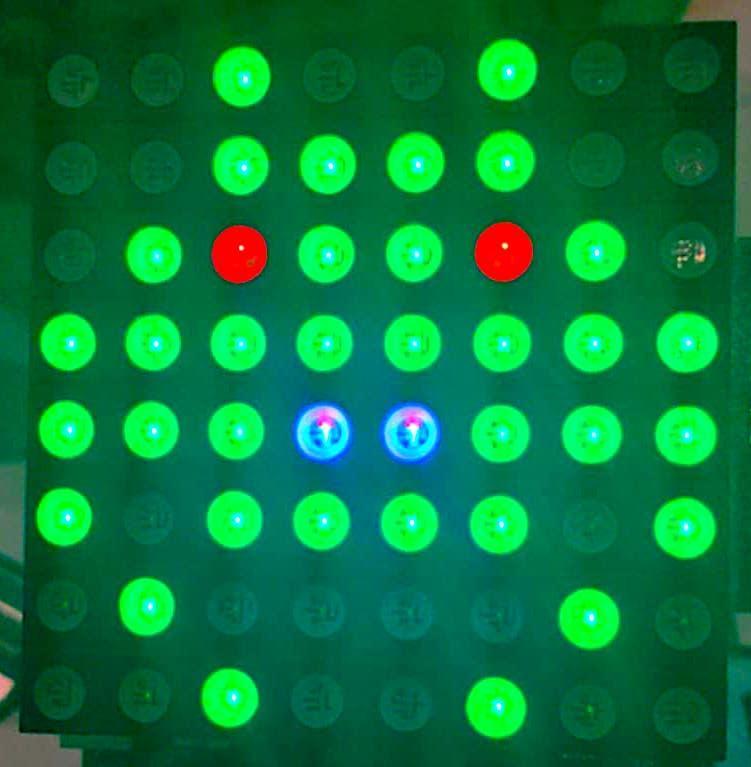
This is what’s displayed with the data below.
LOOP:
    ld iy,RGBDATA
    ld c,62       ;RGBScan
    rst 10h
    jr LOOP

RGBDATA:  .db 00h,00h,24h,00h,18h,00h,00h,00h    ; RED Data
          .db 24h,3Ch,5Ah,0FFh,0FFh,0BDh,42h,24h ; GREEN Data
          .db 00h,00h,00h,00h,18h,00h,00h,00h    ; BLUE Data
Real Time Clock (RTC) Add-On Interface
A RTC add-on board that connects to the General Purpose IO port on the TEC-1G can be interfaced with Mon3. The board uses the DS1302 Real Time Clock chip. The RTC chip is designed to respond on port FCH.
The DS1302 supports 12 and 24 hour clock modes, a 100 year calendar (2000-2099) with leap year support, and 31 bytes of general purpose nonvolatile RAM. The TEC Designers have called the NVRAM, “Parameter RAM” or PRAM.
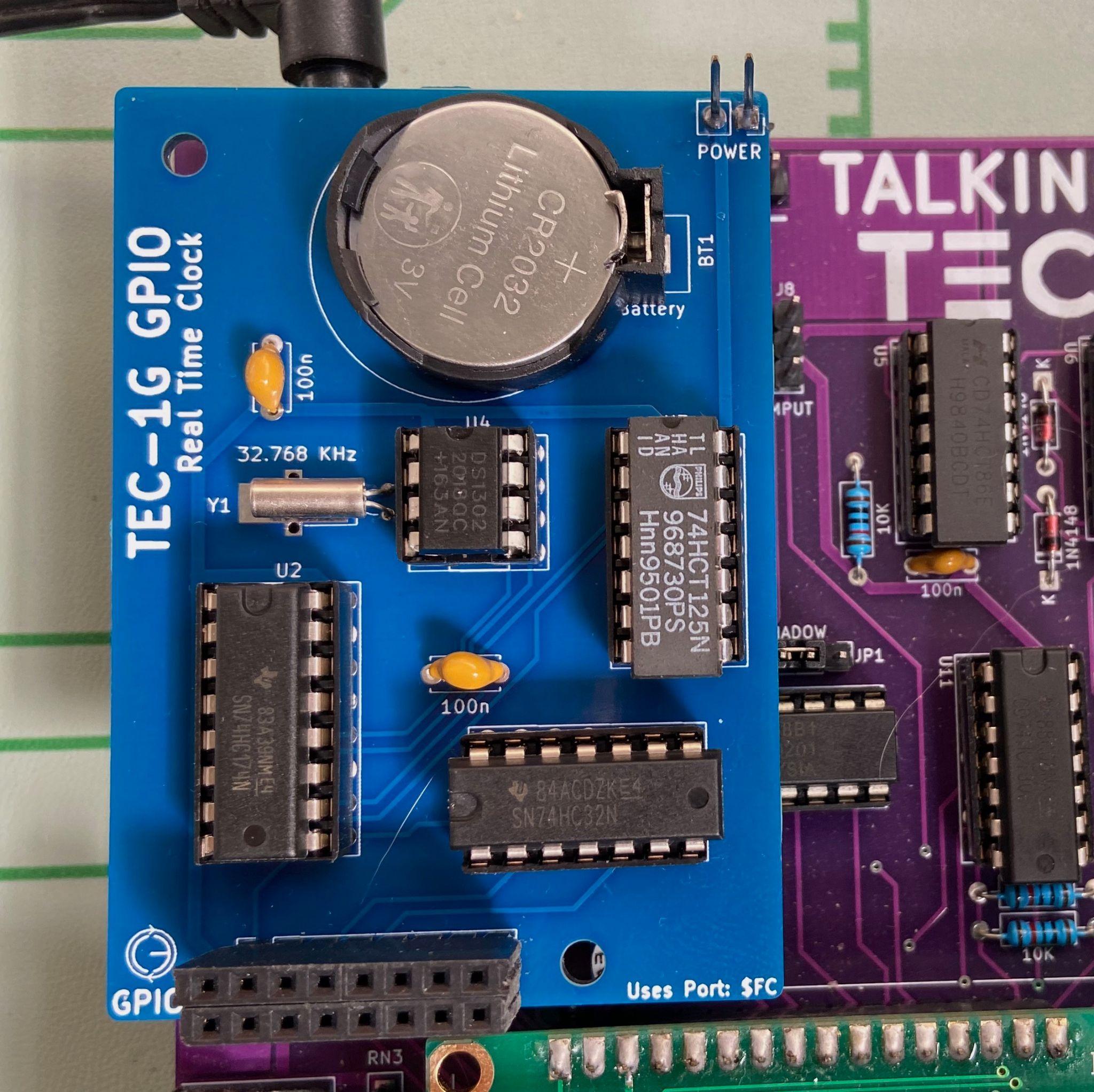
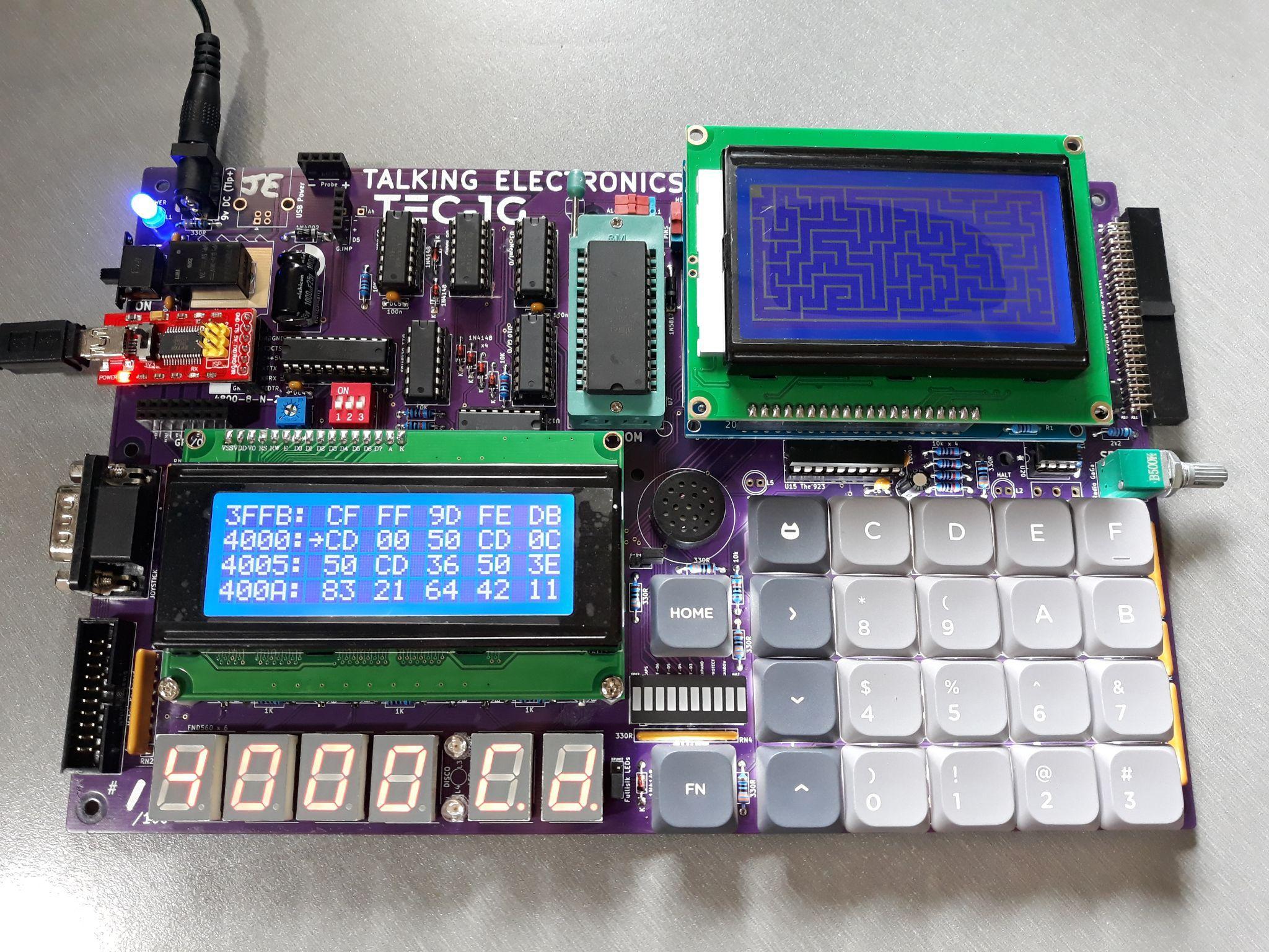
RTC add-on board connected to the TEC-1G GPIO port.
To initially set the RTC, a convenient RTC Setup routine has been provided in the Settings item in the Main Menu. Select “Configure RTC”. Press the following keys to update the time/date: 0 = Hour, 1 = Minute, 2 = Second, 3 = 12/24h, 4 = Day of week, 5 = Day, 6 = Month, 7 = Year, 8 = View RTC PRAM, F = Reset RTC, AD = Exit. When viewing RTC PRAM data, Plus = Move Down, Minus = Move Up, AD = Exit back to RTC Setup.
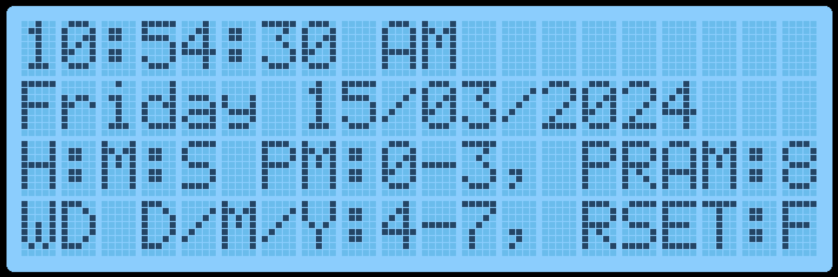
RTC setup display.
Mon3 will automatically utilise the internal PRAM to retain some settings when the TEC-1G is powered down. 14 free bytes are available to be used by the user. The reserved Mon3 PRAM slots are:
| Slot | Reserved for |
|---|---|
0-5 |
Quick Jump Addresses |
6-11 |
Start/End/Dest Addresses |
12-13 |
Baud Rate |
14-15 |
Addr. Inc. / Beep |
16-29 |
User Free RAM |
30 |
Mon3 Checksum |
When the RTC board is first used, TEC-1G settings are saved to the PRAM during power on. Manual resetting of the PRAM can also be achieved by selecting the “Reset RTC & PRAM” option in the Settings item in the Main Menu. This will reset the time/date and Mon3 reserved values.
RTC API Calls
The RTC API uses the standard RST 10H call with the addition of the B
register to specify which RTC API function is required. This way, all RTC
functions only occupy a single Mon3 API call.
General Interface
ld c,2EH       ;RTC API call number
ld b,[RTC Call Number]
rst 10H
Examples
          ;Get the current time
01 2E 02  ld bc,022EH      ;getTime + RTC API
D7        rst 10H

          ;Set the current time to 10:24:46
01 2E 03  ld bc,032EH      ;setTime + RTC API
21 00 30  ld hl,1024H      ;10 hours, 24 minutes
16 46     ld d,46H         ;46 seconds
D7        rst 10H

          ;Write a byte to the RTC NV Ram
01 2E 0C  ld bc,0C2EH      ;writeRTCbyte + RTC API
11 FF 02  ld de,02FFH      ;Save FF in position 02
D7        rst 10H
RTC Routine List
| Routine | # | 0x |
|---|---|---|
checkDS1302 |
0 | 00 |
resetDS1302 |
1 | 01 |
getTime |
2 | 02 |
setTime |
3 | 03 |
getDate |
4 | 04 |
setDate |
5 | 05 |
getDay |
6 | 06 |
setDay |
7 | 07 |
get1224Mode |
8 | 08 |
set12HrMode |
9 | 09 |
set24HrMode |
10 | 0A |
readRTCByte |
11 | 0B |
writeRTCByte |
12 | 0C |
burstRTCRead |
13 | 0D |
BCDToBin |
14 | 0E |
binToBCD |
15 | 0F |
formatTime |
16 | 10 |
formatDate |
17 | 11 |
RTCSetup |
18 | 12 |
checkDS1302 #0 (00H)
Check if a DS1302 is detectable, by verifying that the DS1302’s registers return expected results.
- Input: none
- Output:
Carry flagset = no RTC add-on board present - Destroy:
A
resetDS1302 #1 (01H)
Resets the DS1302 to a known state - clears existing Time and Calendar. Does not clear RTC RAM. Sets DS1302 to 01:00.00 AM, 01/01/2000.
- Input: none
- Destroy: none
Note: To be used only when the RTC requires a settings reset e.g. if it’s not
“ticking”. Use checkDS1302 to “reset” the DS1302 to a ready state, as part of
program initialization.
getTime #2 (02H)
Get time from RTC. Time is formatted in either 12 or 24 hour mode, depending on selected mode.
- Input: none
- Output:
H= hour, bit 5=am/pm flag (in 12hr mode). 1=PM - Output:
L= minute - Output:
D= second - Destroy:
A
Note that all returned registers are BCD coded, so 10:24:36 results in
HL = 1024h, D = 36h.
setTime #3 (03H)
Sets the time in the RTC chip. Time is formatted in either 12 or 24 hour mode, depending on selected mode.
- Input:
H= hour, bit 5=am/pm flag (in 12hr mode). 1=PM - Input:
L= minute - Input:
D= second - Destroy:
A,E
The 12/24 hour mode flag is preserved. Note that all registers are BCD
coded, so 10:24:36 is formatted as HL = 1024h, D = 36h.
getDate #4 (04H)
Returns the present Calendar date, month, year.
- Input: none
- Output:
H= date - Output:
L= month - Output:
DE= year - Destroy:
A
Note that values returned are BCD coded.
setDate #5 (05H)
Sets the Calendar to a specified date/month/year. Invalid dates may be accepted e.g. 30 February as the DS1302 does not validate dates as programmed; it simply rolls over at midnight.
- Input:
H= date - Input:
L= month - Input:
DE= year 2000-2099,Dis assumed to be20h - Destroy:
A
Note that values returned are BCD coded.
getDay #6 (06H)
Gets the Day of the week i.e. “Monday”, “Tuesday”, etc. 01 = Monday, 07 = Sunday.
- Input: none
- Output:
D= 01-07 (Day of week) - Output:
HL= address of zero terminated DOW string - Destroy:
A
The names of the days of the week are stored in the Mon3 ROM; HL points to the correct string for that day.
setDay #7 (07H)
Sets the Day of the week. 01 = Monday, 07 = Sunday.
- Input:
D= 01-07 (Day of week) - Output:
Carry Flagset = invalid value supplied - Destroy:
A
get1224Mode #8 (08H)
Reports if the RTC is currently in 12 or 24 hour mode.
- Input: none
- Output:
A= 00H (24hr), 80H (12hr),Zero flagset - Destroy: none
set12HrMode #9 (09H)
Set RTC to 12 hour mode. That is, the hour is subsequently returned as 01-12, and an AM/PM flag.
- Input: none
- Output:
Carry Flagset = already in 12 hr mode - Destroy:
A,D
set24HrMode #10 (0AH)
Set RTC to 24 hour mode (also known as Military Time). That is, the hour is subsequently returned as 00-23.
- Input: none
- Output:
Carry Flagset = already in 24 hr mode - Destroy:
A,D
readRTCByte #11 (0BH)
Reads a byte from the RTC PRAM.
- Input:
D= memory slot to return 0-30 - Output:
A= value stored in memory - Destroy: none
writeRTCByte #12 (0CH)
Writes a byte to the RTC PRAM.
- Input:
D= memory slot to write to 0-30 - Input:
E= value to store - Destroy:
A
burstRTCRead #13 (0DH)
Reads all 31 RTC PRAM bytes and fills a user-supplied buffer with that data. The user buffer should be 31 bytes long.
- Input:
HL= location to write to (31 bytes) - Output:
HL= moved to address after last byte - Destroy:
A
BCDToBin #14 (0EH)
Converts the value in register A from BCD encoded, to binary. i.e. 23h
becomes 23 decimal.
- Input:
A= BCD Value to convert - Output:
A= Binary value of BCD - Destroy: none
binToBCD #15 (0FH)
Converts the value in register A from binary to BCD. i.e. 52 decimal
becomes 52h.
- Input:
A= Binary Value to convert - Output:
A= BCD value of Binary - Destroy: none
formatTime #16 (10H)
Takes a time and fills a user-supplied buffer with an ASCIIZ string formatted as human-readable text. The user-supplied buffer should be at least 12 bytes long.
Bits 7 and 5 of the hour is used to format the time, if it is a 12hr mode timestamp - AM or PM is appended accordingly.
- Input:
H= hour (bit 7 = 12/24hr, 1=12hr mode; bit 5 = am/pm flag, 1=PM) - Input:
L= minute - Input:
D= second - Input:
IY= address of user supplied buffer - Output:
IY= moved to address after last byte - Destroy:
A
formatDate #17 (11H)
Takes a date and fills a user-supplied buffer with an ASCIIZ string formatted as human-readable text. The user-supplied buffer should be at least 11 bytes long. Dates are output as DD/MM/YYYY
- Input:
H= date - Input:
L= month - Input:
DE= year (2000-2099) - Input:
IY= address of user supplied buffer - Output:
IY= moved to address after last byte - Destroy:
A
RTCSetup #18 (12H)
Standalone application that assists with configuring the RTC for initial use. The LCD displays the current RTC time and date with the instructions.
Keys: 0 = Hour, 1 = Minute, 2 = Second, 3 = 12/24h, 4 = Day of week, 5 = Day, 6 = Month, 7 = Year, 8 = View RTC PRAM, F = Reset RTC, AD = Exit.
When viewing RTC RAM data, Plus = Move Down, Minus = Move Up, AD = Exit back to RTC Setup.
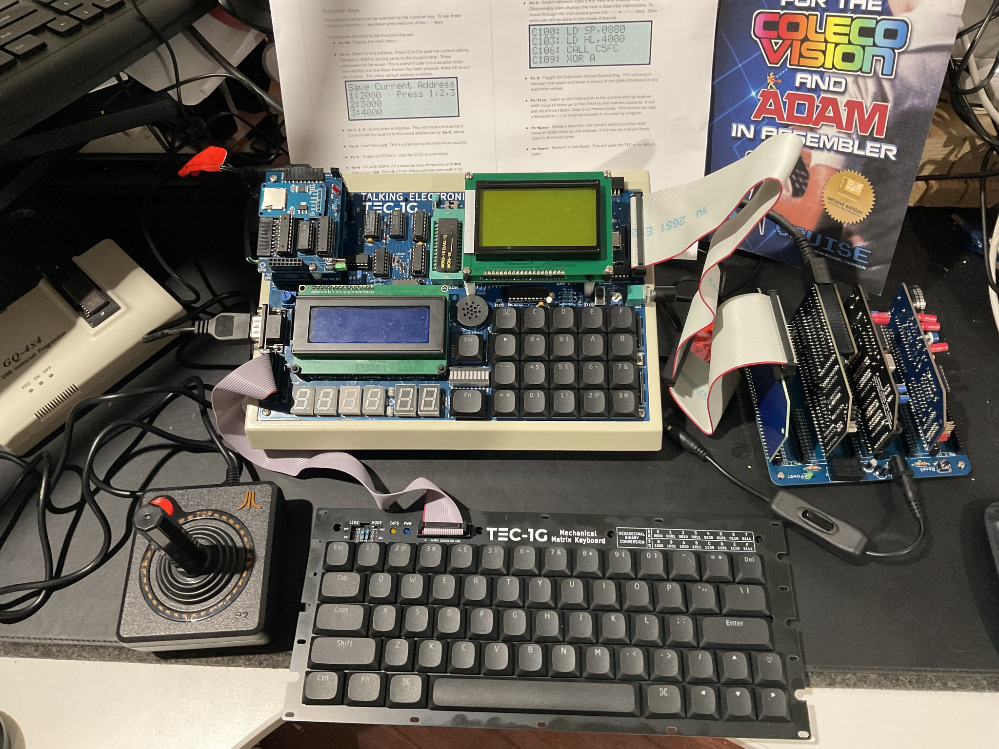
A TEC-1G with various add-on boards. Credit: Andrew McRae.
Graphical LCD Add-On Interface
Mon3 includes a Graphical LCD (GLCD) library that will work with the TEC-DECK Graphical LCD PCB Add-On. If the Graphical LCD is installed on the TEC-1G via the TEC-DECK headers, special GLCD API calls can be used to interface with the GLCD. The library is for GLCDs with the ST7920 chip.
The GLCD library contains a variety of routines that can produce simple shapes and lines. These include text, lines, rectangles, circles and pixels.
General Conventions
The register A holds the API Call number. All other registers except the IX register can be used as parameters if needed. Executing a RST 18H or DF calls the GLCD API.
General Interface
ld a,[API Call Number]
rst 18H
The following code will draw a box and write text to the GLCD
          ; Initialise and set to Graphics Mode
3E 00     ld a,0          ; Initialise GLCD
DF        rst 18H
3E 04     ld a,4          ; Graphics Mode
DF        rst 18H

          ; Draw Box - Box Outline Example
01 20 00  ld bc,0020H     ; X0, Y0
11 3F 7F  ld de,7F3FH     ; X1, Y1
3E 06     ld a,6 ; Draw a outline box from X0,Y0 to X1,Y1
DF        rst 18H

          ; Plot Graphics to LCD Screen (must do)
3E 0C     ld a,12         ; Plot To LCD
DF        rst 18H

          ;Write Text to the Screen
3E 05     ld a,5          ; Text Mode
DF        rst 18H
0E 01     ld c,01H        ; Row 1
3E 0D     ld a,13         ; Print String
DF        rst 18H
54 45 43 2D 31 47 00 .db "TEC-1G",0
initLCD must be called at the start of every program. The GLCD has two modes, Text and Graphics. Both Text and Graphics can be displayed at the same time. These modes must be selected before the drawing or text routine. Also, plotToLCD must be called to display any graphics drawn to the screen. The above example adheres to these principles.
GLCD API Call List
| Routine | # | 0x |
|---|---|---|
initLCD |
0 | 0 |
clearGBUF |
1 | 01 |
clearGrLCD |
2 | 02 |
clearTxtLCD |
3 | 03 |
setGrMode |
4 | 04 |
setTxtMode |
5 | 05 |
drawBox |
6 | 06 |
drawLine |
7 | 07 |
drawCircle |
8 | 08 |
drawPixel |
9 | 09 |
fillBox |
10 | 0A |
fillCircle |
11 | 0B |
plotToLCD |
12 | 0C |
printString |
13 | 0D |
printChars |
14 | 0E |
delayUS |
15 | 0F |
delayMS |
16 | 10 |
setBufClear |
17 | 11 |
setBufNoClear |
18 | 12 |
clearPixel |
19 | 13 |
flipPixel |
20 | 14 |
drawGraphic |
21 | 15 |
invGraphic |
22 | 16 |
initTerminal |
23 | 17 |
sendCharToLCD |
24 | 18 |
sendStringToLCD |
25 | 19 |
sendRegToLCD |
26 | 1A |
sendHLToLCD |
27 | 1B |
setCursor |
28 | 1C |
getCursor |
29 | 1D |
displayCursor |
30 | 1E |
autoLF |
31 | 1F |
underline |
32 | 20 |
plotAlways |
33 | 21 |
GLCD API Configure Calls
initLCD #0 (00H)
Initialise the LCD Screen. This routine is to be called before any other routine.
- Input: nothing
- Destroy: All
clearGBUF #1 (01H)
Clear the Graphics Buffer. The Graphics Buffer or GBUF is the internal memory area that contains pixel data for the LCD. The drawing routines write data to the GBUF. Once all pixels are set, this buffer is then plotted to the LCD with the plotToLCD Routine. Clearing the GBUF is a good way to ensure the pixel area is empty.
- Input: nothing
- Destroy: All
clearGrLCD #2 (02H)
Clear the Graphics LCD Screen. This routine clears the GDRAM or Graphics screen on the LCD.
- Input: nothing
- Destroy: All
clearTxtLCD #3 (03H)
Clear the Text LCD Screen. This routine clears the DDRAM or Text screen on the LCD.
- Input: nothing
- Destroy: All
setGrMode #4 (04H)
Set the LCD to Graphics Mode. This routine puts the LCD in Graphics mode (Extended Instructions). Any further instructions to the LCD will be for the graphics screen. It only needs to be called once if multiple graphics routines are used.
- Input: nothing
- Destroy: AF,DE
setTxtMode #5 (05H)
Set the LCD to Text Mode. This routine puts the LCD in Text mode (Basic Instructions). Any further instructions to the LCD will be for the text screen. It only needs to be called once if multiple text routines are used.
- Input: nothing
- Destroy: AF,DE
GLCD API Graphics Calls
drawBox #6 (06H)
Draws a single-line rectangle between two points X1, Y1 and X2, Y2.
- Input:
B= X1-coordinate (0-127) - Input:
C= Y1-coordinate (0-63) - Input:
D= X2-coordinate (0-127) - Input:
E= Y2-coordinate (0-63) - Destroy:
AF,HL
ld bc,0020H    ;X0, Y0
ld de,7F3FH    ;X1, Y1
ld a,6         ;drawBox
rst 18H
drawLine #7 (07H)
Draws a straight line between X1, Y1 and X2, Y2. Uses the Bresenham Line drawing algorithm.
- Input:
B= X1-coordinate (0-127) - Input:
C= Y1-coordinate (0-63) - Input:
D= X2-coordinate (0-127) - Input:
E= Y2-coordinate (0-63) - Destroy: all
ld bc,0010H    ;X0, Y0
ld de,7F30H    ;X1, Y1
ld a,7         ;drawLine
rst 18H
drawCircle #8 (08H)
Draw a circle from midpoint to radius.
- Input:
B= Mid-X-coordinate (0-127) - Input:
C= Mid-Y-coordinate (0-63) - Input:
E= radius (1-63) - Destroy: all
ld bc,0818H    ;Mid X, Mid Y
ld e,08H       ;Radius
ld a,8         ;drawCircle
rst 18H
drawPixel #9 (09H)
Draws a single Pixel.
- Input:
B= X-coordinate (0-127) - Input:
C= Y-coordinate (0-63) - Destroy:
AF,HL
ld bc,4020H    ;X,Y
ld a,9         ;drawPixel
rst 18H
fillBox #10 (0AH)
Draws a filled rectangle between X1, Y1 and X2, Y2.
- Input:
B= X1-coordinate (0-127) - Input:
C= Y1-coordinate (0-63) - Input:
D= X2-coordinate (0-127) - Input:
E= Y2-coordinate (0-63) - Destroy:
AF,HL
ld bc,0020H    ;X0, Y0
ld de,7F3FH    ;X1, Y1
ld a,10        ;fillBox
rst 18H
fillCircle #11 (0BH)
Draws a filled circle from a midpoint to a radius. This routine iteratively calls the drawCircle routine increasing the radius until it equals the register E. There might be gaps in the filled circle, but hey it looks just like what you get on a BASIC program.
- Input:
B= Mid-X-coordinate (0-127) - Input:
C= Mid-Y-coordinate (0-63) - Input:
E= radius (1-63) - Destroy: all
ld bc,1018H    ;Mid X, Mid Y
ld e,08H       ;Radius
ld a,11        ;fillCircle
rst 18H
plotToLCD #12 (0CH)
This routine draws the Graphics Buffer or GBUF to the Graphics LCD screen. It is usually called after one of the drawing routines is called. This routine must be called for any graphics to appear on the GLCD. After plotting the GBUF is cleared. Use setBufNoClear to retain the GBUF.
- Input: nothing
- Destroy: All
GLCD API Text Calls
printString #13 (0DH)
Prints ASCII text on a given row. There are 4 text rows on the LCD screen. The text is to be defined directly after the RST 18H routine and is to be terminated with a zero.
- Input:
C= row number (0-3) - Input: text string on the next line, terminated with zero
- Destroy: all
ld c,02H       ;Row 2
ld a,13        ;printString
rst 18H
.db 02H, " This Text ", 1BH ,00H
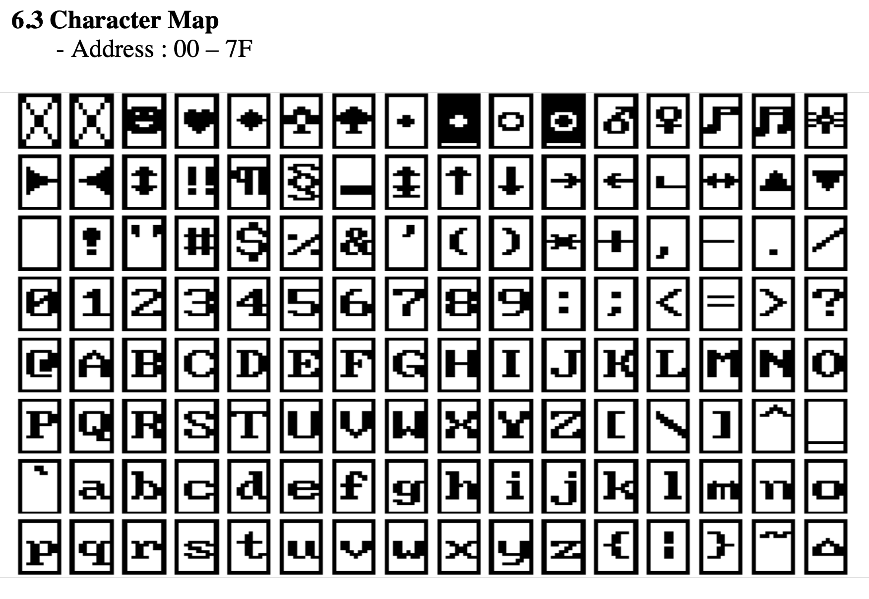
There are 128 characters that are available from 00H-7FH. Conveniently, Alphanumeric characters align with the ASCII table.
printChars #14 (0EH)
Print Characters on the screen in a given row and column. This routine is similar to the one above but character row and column placement can be made. Characters to be printed are to be terminated with a zero.
Even though there are 16 columns, only every second column can be written to and two characters are to be printed. IE: if one character is to be printed in column 2, then set B=0 and print “ x”, putting a space before the character.
- Input:
B= column (0-7) - Input:
C= row (0-3) - Input:
HL= start address of text data - Destroy: all;
HLwill be at the end of the text data
ld hl,TEXT_DATA
ld bc,0102H     ;Column 1, Row 2
ld a,14         ;printChars
rst 18H
...
TEXT_DATA:
.db "Hello!",0
GLCD API Utility Calls
delayUS #15 (0FH)
Delay loop for LCD to complete its instruction. Every time a command is sent to the LDC, it requires a small amount of time to complete that operation. IE: setting extended instruction mode. The time needed for most operations is defined in the LDC specification. It is usually around 72us. This routine is used internally, but can also be used directly. The delay time depends on how fast the CPU is running.
- Input: nothing
- Destroy: AF,DE
  ld a,02H    ;Home instruction
  out (07),a  ;send instruction to GLCD
ld a,15     ;delayUS
rst 18H
delayMS #16 (10H)
This is the same as the above routine, but the delay can be software controlled.
- Input: DE = delay value
- Destroy: AF,DE
  ld a,01H    ;Clear instruction
  out (07),a  ;send instruction to GLCD
  ld de,0050H ;longer delay
ld a,16     ;delayMS
rst 18H
setBufClear #17 (11H)
On every plotToLCD call, clear the graphics buffer GBUF. Calling this routine will clear the graphics buffer on every draw to the LCD. This is useful if doing animation that requires a new drawing to be displayed on every plot or frame.
- Input: none
- Destroy: AF
setBufNoClear #18 (12H)
Do not clear the graphics buffer on every plotToLCD. Calling this routine will not clear the graphics buffer on every draw to LCD. This is useful for adding graphics data to an existing drawing.
- Input: none
- Destroy: AF
clearPixel #19 (13H)
Removes or clears a single Pixel from the LCD.
- Input:
B= X-coordinate (0-127) - Input:
C= Y-coordinate (0-63) - Destroy:
AF,HL
ld bc,4020H     ;X,Y
ld a,19         ;clearPixel
rst 18H
flipPixel #20 (14H)
Inverts a single Pixel. If the Pixel is on, it will turn off. If the Pixel is off, it will turn on.
- Input:
B= X-coordinate (0-127) - Input:
C= Y-coordinate (0-63) - Destroy:
AF,HL
ld bc,4020H     ;X,Y
ld a,20         ;flipPixel
rst 18H
GLCD API Drawing Calls
drawGraphic #21 (15H)
Draw an ASCII character or Sprite to the GLCD at the current cursor. ASCII characters are 6x6 or 5x5 Pixels and most have a gap to the right and bottom for spacing. plotToLCD is still required to be called after all graphics have been drawn.
Graphics data is in the format of up to 16 bytes across and 64 bytes down, where a BIT set will indicate a pixel to be drawn. If graphics are less than 8 bits wide, then bits are read from the least significant bit.
- Input:
D= ASCII number - Input: if
D = 0, thenHL= address of graphic data - Input: if
D = 0, thenB= width of graphic in pixels (1-128) - Input: if
D = 0, thenC= height of graphic in pixels (1-64) - Destroy: all
ld a,00H        ;Custom graphic
ld hl,picture   ;Data table address
ld b,16         ;B=16 pixels wide
ld c,8          ;C=8 pixels down
ld a,21         ;drawGraphic
rst 18H
ld a,12         ;plotToLCD
rst 18H
Graphic data for picture:
picture:
    .db 10000011b,11000001b
    .db 10000100b,00100001b
    .db 10001010b,01010001b
    .db 10001000b,00010001b
    .db 10001010b,01010001b
    .db 10001001b,10010001b
    .db 10000100b,00100001b
    .db 10000011b,11000001b
This example displays the image from the current cursor position.

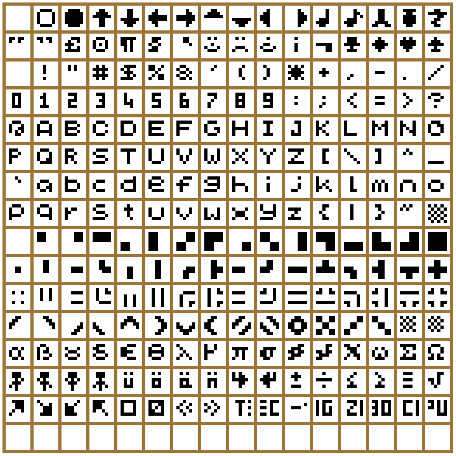
Here is the complete list of ASCII characters 00H-FFH that can be displayed. Each character is up to 6 x 6 pixels and is numbered left to right, top to bottom. The characters align with the standard ASCII Table.
invGraphic #22 (16H)
Inverse graphics printing. Calling this routine will TOGGLE the inverse drawing flag. The initial state is normal. If in inverse mode, a pixel drawn using the drawGraphic routine is displayed if a BIT is not set.
- Input: none
- Output: none
- Destroy: A
underline #32 (20H)
Underline the graphics printing. Calling this routine will TOGGLE the underline drawing flag. The initial state is off. If in underline mode, the last pixel row will be set as on. Only applicable when using the drawGraphic routine.
- Input: none
- Output: none
- Destroy: A
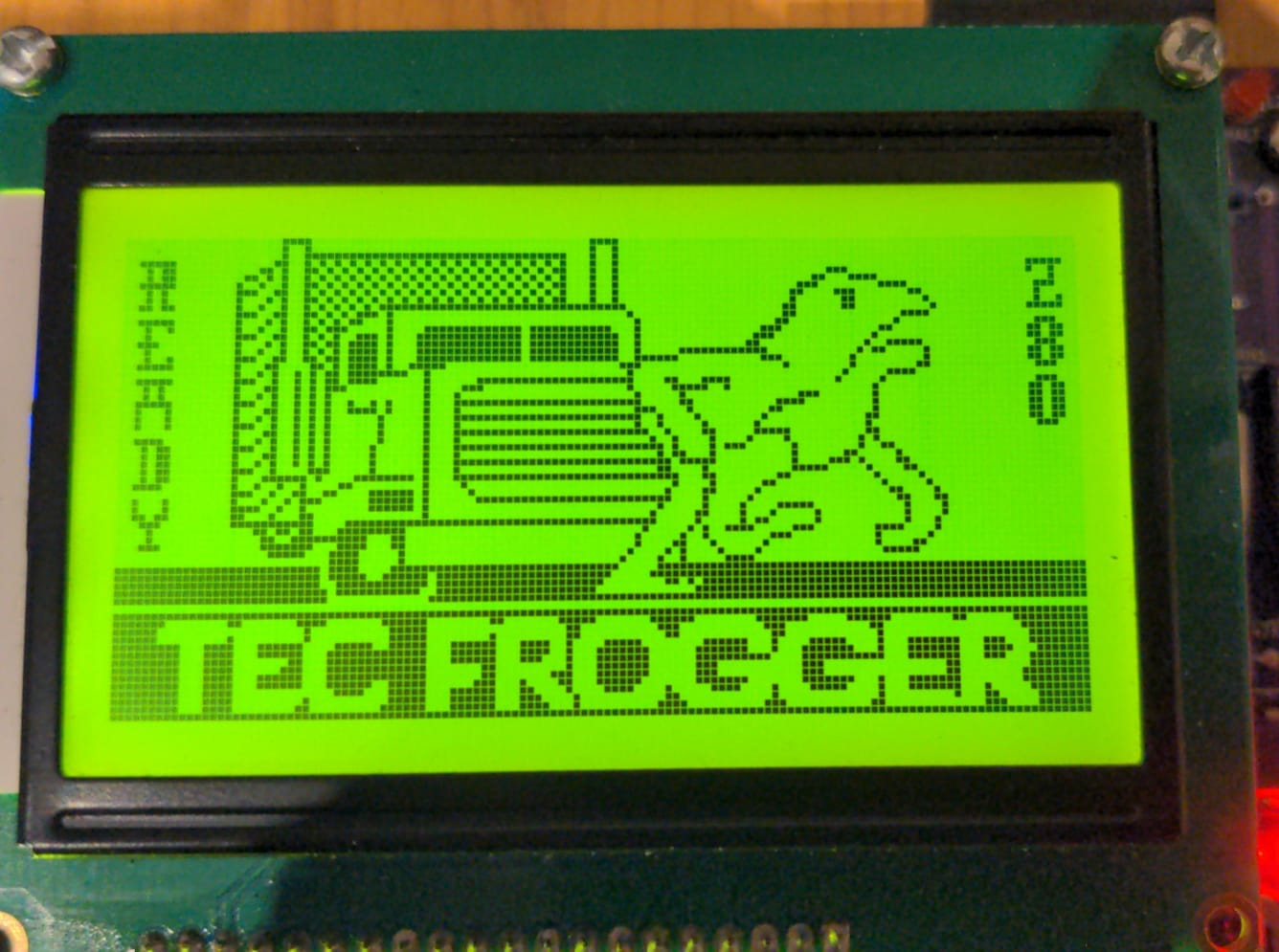
The TEC Frogger game uses the GLCD and its API routines.
GLCD API Terminal Emulator Calls
initTerminal #23 (17H)
Initialise the GLCD for terminal emulation. This routine is to be called before any TERMINAL routine is called. It will set graphics and scroll buffers. It also Clears the GBUF, sets the cursor to top left and displays the cursor. This routine will also call initLCD.
- Input: none
- Output: none
- Destroy: All
autoLF #31 (1FH)
Automatic Line Feed when the cursor reaches the end of the row. When the cursor passes the last column, character entered via the sendCharToLCD will either wrap around, or start on a new line.
- Input: C = 0, Auto LF set, C <> 0, not set
- Output: none
- Destroy: A
plotAlways #33 (21H)
When sendCharToLCD is called, determine if the character should be sent immediately to the GLCD or be held in a buffer. If held in a buffer, call plotToLCD to update the GLCD. The default is ON and characters will be sent immediately. Turning this flag OFF can speed up the output if multiple characters are sent to the screen. Once sent, characters can be plotted all at once. If displaying characters directly from a keyboard input, this flag should be set ON.
- Input: C = 0, Plot Always set, C non zero, not set
- Output: none
- Destroy: A
sendCharToLCD #24 (18H)
Send or handle ASCII characters to the GLCD screen. This routine displays ASCII characters to the GLCD screen and handles some special control characters. It also handles scrolling history of 10 lines. Characters are drawn at the current cursor position. The Cursor will increment when a character is drawn. Characters will automatically be displayed on the LCD. Some special characters are:
CR/0DHmoves the cursor down and resets its column.LF/0AHis ignored.FF/0CHclears the terminal and scroll buffer; destroysAF,BC,DE,HL.BS/08Hdeletes the character at the cursor and moves the cursor back one.HT/09Htabs 4 spaces.UP/05Hscrolls up one line if possible.DN/06Hscrolls down one line if possible.- Input:
C= ASCII character to send to the LCD screen, orC = 0to draw the cursor only - Destroy: all
ld c,65         ;ASCII 'A'
ld a,24         ;sendCharToLCD
rst 18H
ld c,0DH        ;Carriage Return
ld a,24         ;sendCharToLCD
rst 18H
sendStringToLCD #25 (19H)
Send a string of characters to the GLCD. Prints a string pointed by DE at the current cursor. It stops printing and returns when either a CR is printed or when the next byte is the same as what is in register C.
- Input:
C= character to stop printing string - Input:
DE= address of string to print - Destroy: all
ld de,text      ;Text to display
ld c,0          ;terminate on zero
ld a,25         ;sendStringToLCD
rst 18H
text: .db "Hello TEC-1G!",0
sendRegToLCD #26 (1AH)
Display a byte or register in ASCII on the GLCD at the current cursor
- Input: C = byte to convert and display
- Destroy: ALL
ld c,a          ;display register A
ld a,26         ;sendRegToLCD
rst 18H
ld c,7BH        ;display '7B'
ld a,26         ;sendRegToLCD
rst 18H
sendHLToLCD #27 (1BH)
Display the register HL in ASCII on the GLCD at the current cursor
- Input: HL = 2-byte register to convert and display
- Destroy: ALL
ld hl,0A6CH     ;display '0A6C'
ld a,27         ;sendHLToLCD
rst 18H
setCursor #28 (1CH)
Set the Graphic cursor position for Terminal Emulation. Update is ignored if either X,Y input is out of bounds.
- Input:
B= X position in pixels (0-127) - Input:
C= Y position in pixels (0-63) - Destroy:
A
ld bc,4020H     ;cursor at X=64, Y=32 (middle of screen)
ld a,28         ;setCursor
rst 18H
getCursor #29 (1DH)
Get the current cursor position
- Input: none
- Output:
B= X position in pixels (0-127) - Output:
C= Y position in pixels (0-63)
displayCursor #30 (1EH)
Turn the cursor ON or OFF. Default is Cursor ON
- Input: C = 0, Turn cursor on, C=non zero, turn cursor off
- Destroy: ALL
GLCD Examples
Provided in the TEC-1G GitHub repository are three GLCD programs. The programs have already been converted to Intel Hex files and are ready to load onto the TEC. All programs start at address 2000H. Source code for all programs are provided and can be changed and studied.
The TEC-1G GitHub account is here: TEC-1G GitHub repository and the GLCD examples are in the TEC-Deck/Graphical_LCD directory.
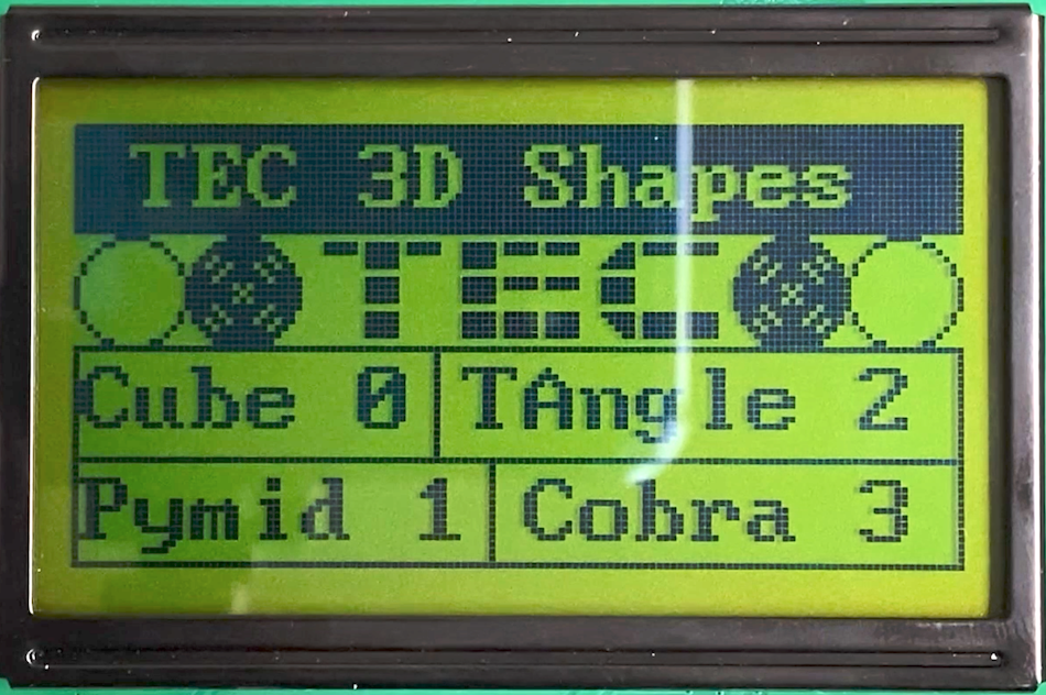
lcd_3d_demo
Draw 3D wireframe graphics and rotate them. This program requires keypad input to rotate the objects. Buttons 4,8 and C rotate the object in the 3-axis. Plus and Minus will zoom the object in and out. 0 will return to the main menu. Pressing GO will exit the program
lcd_mad_program
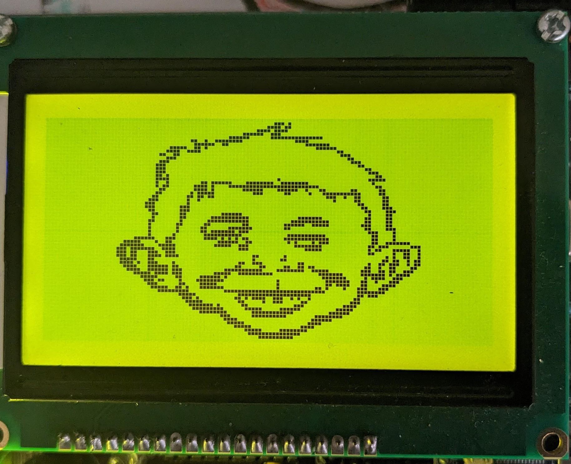
Draw Alfred E. Neuman’s face. This program draws lines between two points and creates the face of the Mad Magazine mascot. It draws one line at a time, similar to how it would display on an Apple ][. But if the program is run at 2022H it will generate instantly. See Meat Fighter’s Mad Magazine demo notes.
lcd_maze_gen
Create a maze. This program generates a maze using a recursive backtracking algorithm. Watch the maze slowly generate before your eyes.
Some easy-to-type examples have also been provided in the Quick Start Programs chapter below.