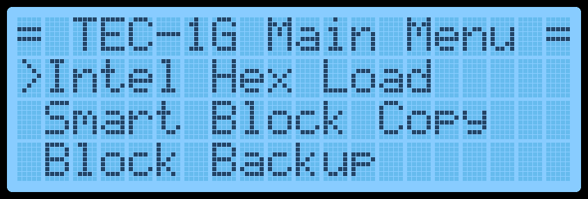
Main Menu
A menu is provided on the LCD screen to help navigate some of the built-in routines within the monitor. The menu will appear on a Cold Reset.
Navigating the menu should be intuitive. Press the Plus or Minus keys to scroll down and up. Press GO to run the selected routine. A right-facing Arrow indicates which menu item is currently selected. Something that might not be obvious is how to exit the menu and change into Data Entry mode. This is achieved by pressing the AD key. Once this is known, it’s hard to forget it. Menus can be nested up to 3 deep. Pressing the AD key will exit to the parent menu or enter Data Entry mode if at the main menu.
The current items on the menu are:
 Menu Text                       Description

 Intel HEX Load                  Receive data in Intel Hex File format via the
                                 FTDI connector

 Drive Access                    Catalog and load files from PATA or SD Card
                                 Expansion boards.  Save and restore the
                                 session.

 Smart Block Copy                Move a block of code AND update all 2-byte
                                 addresses that are within the block

 Block Backup                    Move a block of code

 Export Z80 Assembly             Display Z80 Assembly to a Serial terminal via
                                 the FTDI connector

 Export Raw Data                 Send binary data via the FTDI connector
Intel HEX Load
Drive Access
Smart Block Copy
 Export Hex Dump                  Display a 16-byte per line HEX dump to a Serial
                                  terminal via the FTDI connector

 Import Binary File               Receive data in binary format via the FTDI
                                  connector

 Music Routine                    Play musical notes at a given address

 Settings                         Update monitor settings

 Credits                          Display the people who made the TEC-1G
Intel HEX Load
Intel created a text file format that contains information on loading bytes into memory. When this routine is run, the TEC seven segments will go blank and wait for a file to be received. This is done via the FTDI connector and serial terminal. When data is transmitted, the rightmost segment will illuminate in a pattern. This indicates data is being read. Once the file has fully loaded, the letters “PASS” will display on the seven segments. This means that the load was successful. Press any key to exit. If the segments display the word “FAIL”, then there is something wrong with the file or your serial connection.
Drive Access
With a PATA drive or Micro SD card expansion boards installed, access the files on the drive and load them to the TEC. For more information refer to the Hard Drive Access section for detailed usage information.
Smart Block Copy
This clever routine shifts a program from one memory location to another and changes all absolute jumps and calls. Memory pointers are also altered if the memory pointers are within the start and end address of the program being relocated. Any reference to a location outside the start and end range is not altered.
The block copy treats Data bytes as instructions and might change data bytes. IE: .db C3, 23, 01 could be seen as a JP 0123 instruction.
Block Backup
Export Z80 Assembly
When this routine is run, it will ask for a START, END and DESTINATION address. Type in the 16-bit address via the HEX PAD and use the Plus or Minus keys to change the selected parameter. Press GO to run the routine.
Here is an example of copying 4000H-4009H to location 2000H
 Original                                   After Copy

 4000 11 09 40      LD DE,4009              2000 11 09 20      LD DE,2009
 4003 E7            RST 20                  2003 E7            RST 20
 4004 FE 13         CP 13                   2004 FE 13         CP 13
 4006 C2 00 40      JP NZ,4000              2006 C2 00 20      JP NZ,2000
 4009 C9            RET                     2009 C9            RET
Block Backup
This routine simply copies a data block from one address location to another. No bytes are altered during this copy routine.. This routine is useful to copy data reference tables, like music data, for the music routine.
When this routine is run, it will ask for a START, END and DESTINATION address. Type in the 16-bit address via the HEX PAD and use the Plus or Minus keys to change the selected parameter. Press GO to run the routine.
Here is an example of copying 4000H-4009H to location 2000H
 Original                                   After Copy

 4000 11 09 40      LD DE,4009              2000 11 09 40      LD DE,4009
 4003 E7            RST 20                  2003 E7            RST 20
 4004 FE 13         CP 13                   2004 FE 13         CP 13
 4006 C2 00 40      JP NZ,4000              2006 C2 00 40      JP NZ,4000
 4009 C9            RET                     2009 C9            RET
Export Z80 Assembly If the TEC is connected to a serial terminal via an FTDI to USB adaptor, code that is stored or written on the TEC can be disassembled and sent to the terminal. This is a great way to view the code that is on the TEC in a readable format and could be passed into a Z80 compiler on a PC.
Export Raw Data
Export Hex Dump
When this routine is run, it will ask for a START and END address. Type in the 16-bit address via the HEX PAD and use the Plus or Minus keys to change the selected parameter. Press GO to run the routine.
Here is an example of its output.
 4000 3E 3F         LD A,3F
 4002 D3 01         OUT (02),A
 4004 3E 04         LD A,04
 4006 D3 02         OUT (02),A
 4008 CF            RST 08
 4009 C9            RET
Export Raw Data
This routine will send TEC binary data to a serial connection. It’s a way to save code written on the TEC to a PC. As binary data is being sent, the data can only be properly viewed through a HEX file viewer or HEX dump routine.
When this routine is run, it will ask for a START and END address. Type in the 16-bit address via the HEX PAD and use the Plus or Minus keys to change the selected parameter. Press GO to run the routine.
Export Hex Dump
This routine displays binary data in a readable format to a serial terminal connected via an FTDI to USB adaptor. It will display up to 16 bytes per line.
When this routine is run, it will ask for a START and END address. Type in the 16-bit address via the HEX PAD and use the Plus or Minus keys to change the selected parameter. Press GO to run the routine.
Here is an example of its output.
      C100: 31 80 08 21 00 40 CD FC C5 AF D3 05 D3 06 DB 03
      C110: 47 E6 10 C2 00 80 3A 9F 08 E6 04 0E 01 B1 D3 FF
      C120: 32 9D 08 78 E6 02 32 9E 08 3A 9D 08 E6 01 28 0B
      C130: 21 00 C0 11 00 00 01 00 01 ED B0 21 00 40 22 86
      C140: 08 22 A0 08 DB 03 0F 38 06 DB 00 E6 20 18 08 CD
Import Binary File
Music Routine
This routine will upload a binary file from a PC onto the TEC via an FTDI to USB adaptor. This is the opposite of the Export Raw Data routine and will load binary data to a given address on the TEC.
When this routine is executed, it will ask for a START and END address. This address range must match the size of the binary file being sent. Type in the 16-bit address via the HEX PAD and use the Plus or Minus keys to change the selected parameter. Press GO to run the routine. The TEC will wait for data to be received and will end when END-START+1 bytes are received.
Music Routine
Use this routine to play some notes to the TEC speaker. It is based on John Hardy’s Mon1 routine adjusted for a 4 MHz clock speed. The routine uses similar input codes, making it suitable for existing tunes to be used.
When this routine is executed, it will ask for a START address of the music data-type in the 16-bit address via the HEX PAD. Press GO to run the routine.
Two octaves are playable. Here is a reference to the note code and its musical note. A Pause is represented by 00, and any other note code that isn’t listed will exit the routine.
  Note        Code        Note       Code        Note       Code        Note        Code

    G          01          C#          07          G          0D          C#         13

    G#         02           D          08         G#          0E          D          14

    A          03          D#          09          A          0F         D#          15

    A#         04           E          0A         A#          10          E          16

    B          05           F          0B          B          11          F          17

    C          06          F#          0C          C          12          F#         18
The following page contains examples tunes that can be typed in a played
Bealach 06, 06, 0A, 0D, 06, 0D, 0A, 0D, 12, 16, 14, 12, 0F, 11, 12, 0F 0D, 0D, 0D, 0A, 12, 0F, 0D, 0A, 08, 06, 08, 0A, 0F, 0A, 0D, 0F 06, 06, 0A, 0D, 06, 0D, 0A, 0D, 12, 16, 14, 12, 0F, 11, 12, 0F 0D, 0D, 0D, 0A, 12, 0F, 0D, 0A, 08, 06, 08, 0A, 06, 12, 00, 1F
Angels On High 0F, 0F, 0F, 0F, 0F, 0F, 12, 12, 12, 12, 12, 10, 0F, 0F, 0F, 0F 0F, 0F, 0D, 0D, 0F, 0F, 12, 12, 0F, 0F, 0F, 0D, 0B, 0B, 0B, 0B 0F, 0F, 0F, 0F, 0F, 0F, 12, 12, 12, 12, 12, 10, 0F, 0F, 0F, 0F 0F, 0F, 0D, 0D, 0F, 0F, 12, 12, 0F, 0F, 0F, 0D, 0B, 0B, 0B, 0B 12, 12, 12, 12, 14, 12, 10, 0F, 10, 10, 10, 10, 12, 10, 0F, 0D 0F, 0F, 0F, 0F, 10, 0F, 0D, 0B, 0D, 0D, 0D, 06, 06, 06, 06, 06 0B, 0B, 0D, 0D, 0F, 0F, 10, 10, 0F, 0F, 0F, 0F, 0D, 0D, 00, 00 00, 12, 12, 12, 12, 14, 12, 10, 0F, 10, 10, 10, 10, 12, 10, 0F 0D, 0F, 0F, 0F, 0F, 10, 0F, 0D, 0B, 0D, 0D, 0D, 06, 06, 06, 06 06, 0B, 0B, 0D, 0D, 0F, 0F, 10, 10, 0F, 0F, 0F, 0F, 0D, 0D, 0D 0D, 0B, 0B, 0B, 0B, 0B, 0B, 0B, 0B, 00, 00, 00, 00, 00, 00, 1F
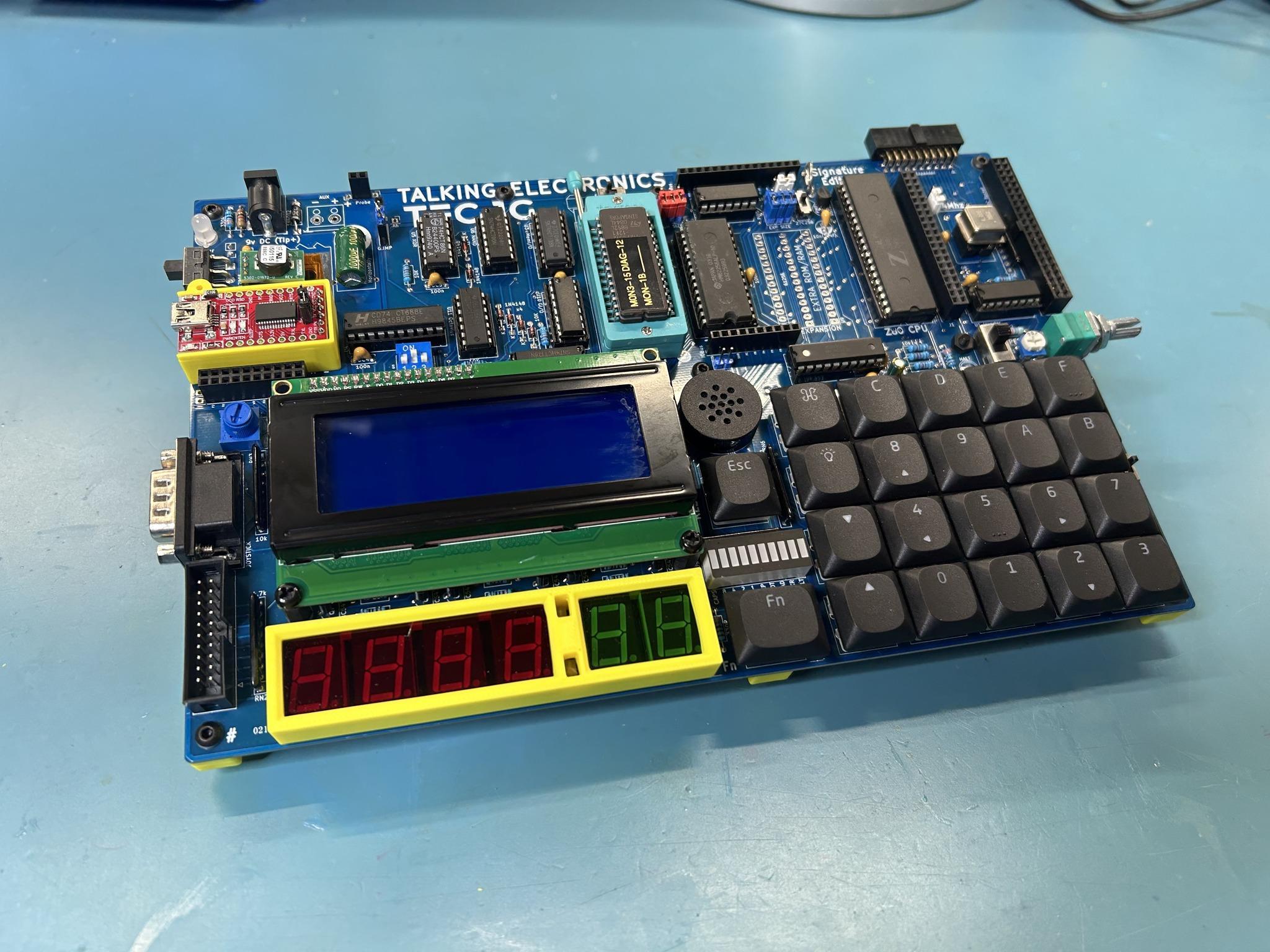
TEC-1G with 3D printed stand and supports. Credit: Gerald M Eberhardt
Settings
Credits
The settings allow the user to configure the monitor. Powering off the TEC will return these settings to their default state. Some settings will be retained if an RTC Add-on board is connected with battery backup.
- Toggle Key Beep - Turn the keypress ‘beep’ indication on or off.
- Set Baud Rate - Modify the Baud rate for serial transmission.
- Toggle GLCD Term - Use the GLCD (if fitted) as a terminal
- Toggle Address Inc - Turn the automatic address increase after a byte ```asm has been keyed on or off.
- Configure RTC - Set Time/Date of RTC (if RTC Add-on is connected).
- Reset RTC & PRAM - Reset RTC for initial use and initialise NVRAM.
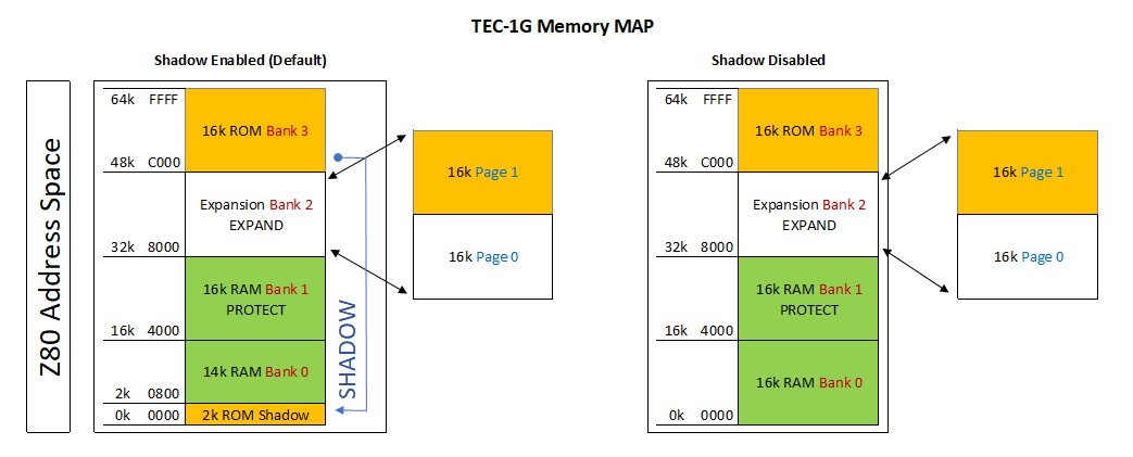
- Toggle EXPAND - software controlled the expansion socket to toggle between lower and upper 16Kb memory for a 32Kb ROM/RAM chip. ```
Credits
Display the people who developed and tested the TEC-1G
- Mark Jelic - Designer of the TEC-1G
- Brian Chiha - Mon3 Programmer 🥚
- Craig Hart - TECnical Expert
- Ian McLean - Tester and QA
- James Elphick - Tester and QA
- John Hardy & Ken Stone - The original designers