Graphical LCD Add-On
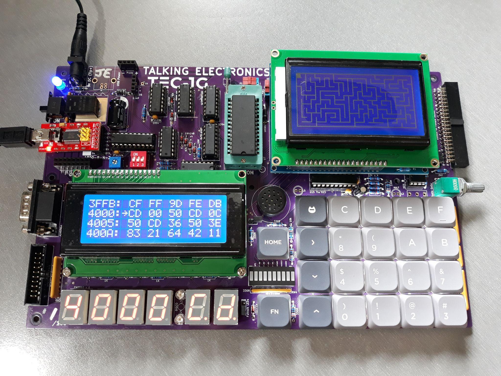
Mon3 includes a Graphical LCD (GLCD) library that will work with the TEC-DECK Graphical LCD PCB Add-On. If the Graphical LCD is installed on the TEC-1G via the TEC-DECK headers, special GLCD API calls can be used to interface with the GLCD. The library is for GLCDs with the ST7920 chip.
The GLCD library contains a variety of routines that can produce simple shapes and lines. These include text, lines, rectangles, circles and pixels.
General Conventions
The register A holds the API Call number. All other registers except the IX register can be used as parameters if needed. Executing a RST 18H or DF calls the GLCD API.
General Interface
ld a,[API Call Number]
rst 18H
The following code will draw a box and write text to the GLCD
          ; Initialise and set to Graphics Mode
3E 00     ld a,0          ; Initialise GLCD
DF        rst 18H
3E 04     ld a,4          ; Graphics Mode
DF        rst 18H

          ; Draw Box - Box Outline Example
01 20 00  ld bc,0020H     ; X0, Y0
11 3F 7F  ld de,7F3FH     ; X1, Y1
3E 06     ld a,6 ; Draw a outline box from X0,Y0 to X1,Y1
DF        rst 18H

          ; Plot Graphics to LCD Screen (must do)
3E 0C     ld a,12         ; Plot To LCD
DF        rst 18H

          ;Write Text to the Screen
3E 05     ld a,5          ; Text Mode
DF        rst 18H
0E 01     ld c,01H        ; Row 1
3E 0D     ld a,13         ; Print String
DF        rst 18H
54 45 43 2D 31 47 00 .db "TEC-1G",0
initLCD must be called at the start of every program. The GLCD has two modes, Text and Graphics. Both Text and Graphics can be displayed at the same time. These modes must be selected before the drawing or text routine. Also, plotToLCD must be called to display any graphics drawn to the screen. The above example adheres to these principles.
GLCD API Call List
| Routine | # | 0x |
|---|---|---|
initLCD |
0 | 0 |
clearGBUF |
1 | 01 |
clearGrLCD |
2 | 02 |
clearTxtLCD |
3 | 03 |
setGrMode |
4 | 04 |
setTxtMode |
5 | 05 |
drawBox |
6 | 06 |
drawLine |
7 | 07 |
drawCircle |
8 | 08 |
drawPixel |
9 | 09 |
fillBox |
10 | 0A |
fillCircle |
11 | 0B |
plotToLCD |
12 | 0C |
printString |
13 | 0D |
printChars |
14 | 0E |
delayUS |
15 | 0F |
delayMS |
16 | 10 |
setBufClear |
17 | 11 |
setBufNoClear |
18 | 12 |
clearPixel |
19 | 13 |
flipPixel |
20 | 14 |
drawGraphic |
21 | 15 |
invGraphic |
22 | 16 |
initTerminal |
23 | 17 |
sendCharToLCD |
24 | 18 |
sendStringToLCD |
25 | 19 |
sendRegToLCD |
26 | 1A |
sendHLToLCD |
27 | 1B |
setCursor |
28 | 1C |
getCursor |
29 | 1D |
displayCursor |
30 | 1E |
autoLF |
31 | 1F |
underline |
32 | 20 |
plotAlways |
33 | 21 |
GLCD API Configure Calls
initLCD #0 (00H)
Initialise the LCD Screen. This routine is to be called before any other routine.
- Input: nothing
- Destroy: All
clearGBUF #1 (01H)
Clear the Graphics Buffer. The Graphics Buffer or GBUF is the internal memory area that contains pixel data for the LCD. The drawing routines write data to the GBUF. Once all pixels are set, this buffer is then plotted to the LCD with the plotToLCD Routine. Clearing the GBUF is a good way to ensure the pixel area is empty.
- Input: nothing
- Destroy: All
clearGrLCD #2 (02H)
Clear the Graphics LCD Screen. This routine clears the GDRAM or Graphics screen on the LCD.
- Input: nothing
- Destroy: All
clearTxtLCD #3 (03H)
Clear the Text LCD Screen. This routine clears the DDRAM or Text screen on the LCD.
- Input: nothing
- Destroy: All
setGrMode #4 (04H)
Set the LCD to Graphics Mode. This routine puts the LCD in Graphics mode (Extended Instructions). Any further instructions to the LCD will be for the graphics screen. It only needs to be called once if multiple graphics routines are used.
- Input: nothing
- Destroy: AF,DE
setTxtMode #5 (05H)
Set the LCD to Text Mode. This routine puts the LCD in Text mode (Basic Instructions). Any further instructions to the LCD will be for the text screen. It only needs to be called once if multiple text routines are used.
- Input: nothing
- Destroy: AF,DE
GLCD API Graphics Calls
drawBox #6 (06H)
Draws a single-line rectangle between two points X1, Y1 and X2, Y2.
- Input:
B= X1-coordinate (0-127) - Input:
C= Y1-coordinate (0-63) - Input:
D= X2-coordinate (0-127) - Input:
E= Y2-coordinate (0-63) - Destroy:
AF,HL
ld bc,0020H    ;X0, Y0
ld de,7F3FH    ;X1, Y1
ld a,6         ;drawBox
rst 18H
drawLine #7 (07H)
Draws a straight line between X1, Y1 and X2, Y2. Uses the Bresenham Line drawing algorithm.
- Input:
B= X1-coordinate (0-127) - Input:
C= Y1-coordinate (0-63) - Input:
D= X2-coordinate (0-127) - Input:
E= Y2-coordinate (0-63) - Destroy: all
ld bc,0010H    ;X0, Y0
ld de,7F30H    ;X1, Y1
ld a,7         ;drawLine
rst 18H
drawCircle #8 (08H)
Draw a circle from midpoint to radius.
- Input:
B= Mid-X-coordinate (0-127) - Input:
C= Mid-Y-coordinate (0-63) - Input:
E= radius (1-63) - Destroy: all
ld bc,0818H    ;Mid X, Mid Y
ld e,08H       ;Radius
ld a,8         ;drawCircle
rst 18H
drawPixel #9 (09H)
Draws a single Pixel.
- Input:
B= X-coordinate (0-127) - Input:
C= Y-coordinate (0-63) - Destroy:
AF,HL
ld bc,4020H    ;X,Y
ld a,9         ;drawPixel
rst 18H
fillBox #10 (0AH)
Draws a filled rectangle between X1, Y1 and X2, Y2.
- Input:
B= X1-coordinate (0-127) - Input:
C= Y1-coordinate (0-63) - Input:
D= X2-coordinate (0-127) - Input:
E= Y2-coordinate (0-63) - Destroy:
AF,HL
ld bc,0020H    ;X0, Y0
ld de,7F3FH    ;X1, Y1
ld a,10        ;fillBox
rst 18H
fillCircle #11 (0BH)
Draws a filled circle from a midpoint to a radius. This routine iteratively calls the drawCircle routine increasing the radius until it equals the register E. There might be gaps in the filled circle, but hey it looks just like what you get on a BASIC program.
- Input:
B= Mid-X-coordinate (0-127) - Input:
C= Mid-Y-coordinate (0-63) - Input:
E= radius (1-63) - Destroy: all
ld bc,1018H    ;Mid X, Mid Y
ld e,08H       ;Radius
ld a,11        ;fillCircle
rst 18H
plotToLCD #12 (0CH)
This routine draws the Graphics Buffer or GBUF to the Graphics LCD screen. It is usually called after one of the drawing routines is called. This routine must be called for any graphics to appear on the GLCD. After plotting the GBUF is cleared. Use setBufNoClear to retain the GBUF.
- Input: nothing
- Destroy: All
GLCD API Text Calls
printString #13 (0DH)
Prints ASCII text on a given row. There are 4 text rows on the LCD screen. The text is to be defined directly after the RST 18H routine and is to be terminated with a zero.
- Input:
C= row number (0-3) - Input: text string on the next line, terminated with zero
- Destroy: all
ld c,02H       ;Row 2
ld a,13        ;printString
rst 18H
.db 02H, " This Text ", 1BH ,00H
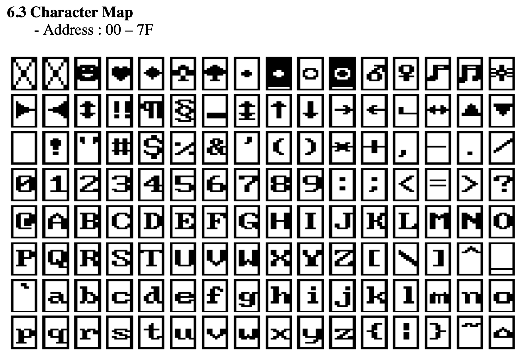
There are 128 characters that are available from 00H-7FH. Conveniently, Alphanumeric characters align with the ASCII table.
printChars #14 (0EH)
Print Characters on the screen in a given row and column. This routine is similar to the one above but character row and column placement can be made. Characters to be printed are to be terminated with a zero.
Even though there are 16 columns, only every second column can be written to and two characters are to be printed. IE: if one character is to be printed in column 2, then set B=0 and print “ x”, putting a space before the character.
- Input:
B= column (0-7) - Input:
C= row (0-3) - Input:
HL= start address of text data - Destroy: all;
HLwill be at the end of the text data
ld hl,TEXT_DATA
ld bc,0102H     ;Column 1, Row 2
ld a,14         ;printChars
rst 18H
...
TEXT_DATA:
.db "Hello!",0
GLCD API Utility Calls
delayUS #15 (0FH)
Delay loop for LCD to complete its instruction. Every time a command is sent to the LDC, it requires a small amount of time to complete that operation. IE: setting extended instruction mode. The time needed for most operations is defined in the LDC specification. It is usually around 72us. This routine is used internally, but can also be used directly. The delay time depends on how fast the CPU is running.
- Input: nothing
- Destroy: AF,DE
  ld a,02H    ;Home instruction
  out (07),a  ;send instruction to GLCD
ld a,15     ;delayUS
rst 18H
delayMS #16 (10H)
This is the same as the above routine, but the delay can be software controlled.
- Input: DE = delay value
- Destroy: AF,DE
  ld a,01H    ;Clear instruction
  out (07),a  ;send instruction to GLCD
  ld de,0050H ;longer delay
ld a,16     ;delayMS
rst 18H
setBufClear #17 (11H)
On every plotToLCD call, clear the graphics buffer GBUF. Calling this routine will clear the graphics buffer on every draw to the LCD. This is useful if doing animation that requires a new drawing to be displayed on every plot or frame.
- Input: none
- Destroy: AF
setBufNoClear #18 (12H)
Do not clear the graphics buffer on every plotToLCD. Calling this routine will not clear the graphics buffer on every draw to LCD. This is useful for adding graphics data to an existing drawing.
- Input: none
- Destroy: AF
clearPixel #19 (13H)
Removes or clears a single Pixel from the LCD.
- Input:
B= X-coordinate (0-127) - Input:
C= Y-coordinate (0-63) - Destroy:
AF,HL
ld bc,4020H     ;X,Y
ld a,19         ;clearPixel
rst 18H
flipPixel #20 (14H)
Inverts a single Pixel. If the Pixel is on, it will turn off. If the Pixel is off, it will turn on.
- Input:
B= X-coordinate (0-127) - Input:
C= Y-coordinate (0-63) - Destroy:
AF,HL
ld bc,4020H     ;X,Y
ld a,20         ;flipPixel
rst 18H
GLCD API Drawing Calls
drawGraphic #21 (15H)
Draw an ASCII character or Sprite to the GLCD at the current cursor. ASCII characters are 6x6 or 5x5 Pixels and most have a gap to the right and bottom for spacing. plotToLCD is still required to be called after all graphics have been drawn.
Graphics data is in the format of up to 16 bytes across and 64 bytes down, where a BIT set will indicate a pixel to be drawn. If graphics are less than 8 bits wide, then bits are read from the least significant bit.
- Input:
D= ASCII number - Input: if
D = 0, thenHL= address of graphic data - Input: if
D = 0, thenB= width of graphic in pixels (1-128) - Input: if
D = 0, thenC= height of graphic in pixels (1-64) - Destroy: all
ld a,00H        ;Custom graphic
ld hl,picture   ;Data table address
ld b,16         ;B=16 pixels wide
ld c,8          ;C=8 pixels down
ld a,21         ;drawGraphic
rst 18H
ld a,12         ;plotToLCD
rst 18H
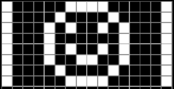
Graphic data for picture:
picture:
    .db 10000011b,11000001b
    .db 10000100b,00100001b
    .db 10001010b,01010001b
    .db 10001000b,00010001b
    .db 10001010b,01010001b
    .db 10001001b,10010001b
    .db 10000100b,00100001b
    .db 10000011b,11000001b
This example displays the image from the current cursor position.
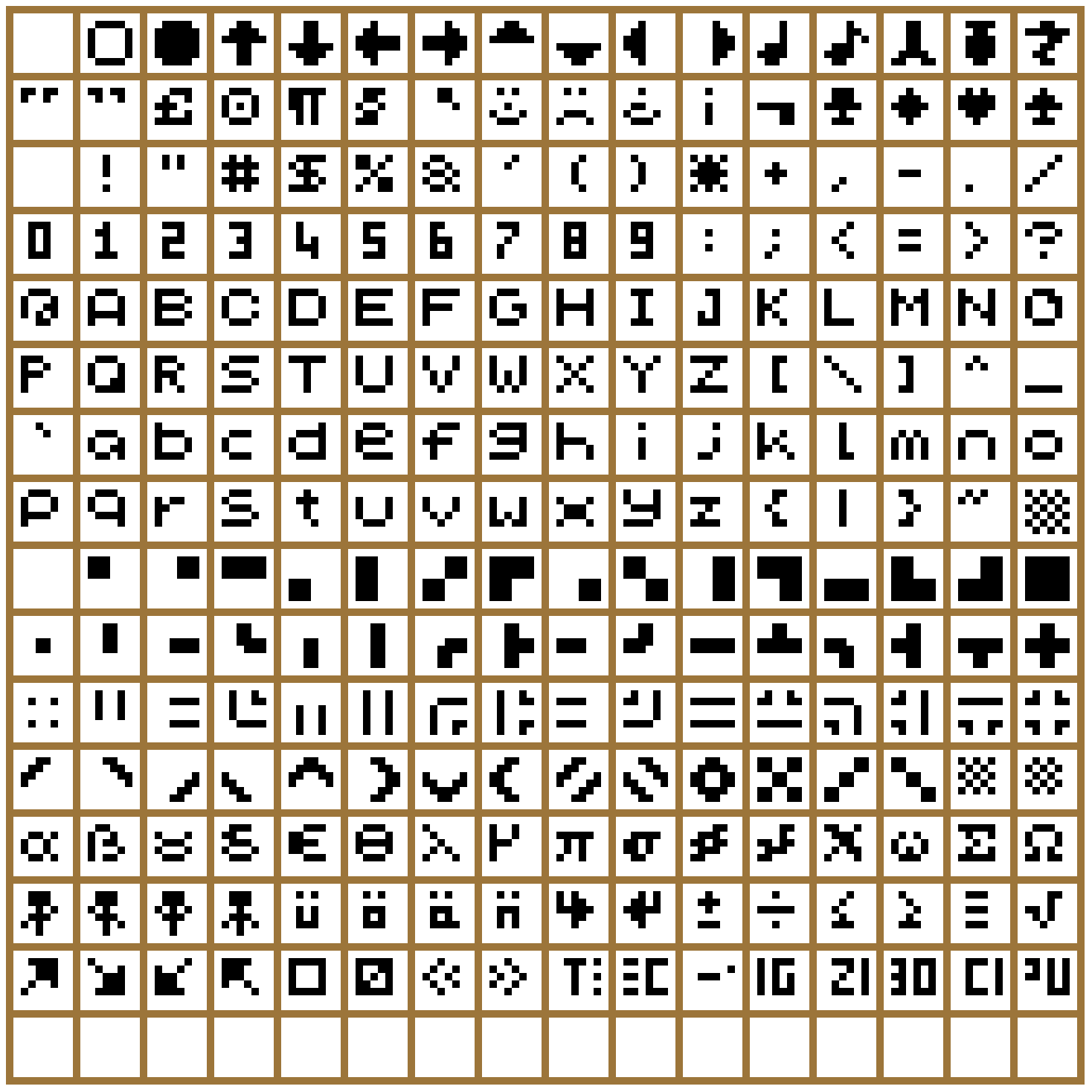
Here is the complete list of ASCII characters 00H-FFH that can be displayed. Each character is up to 6 x 6 pixels and is numbered left to right, top to bottom. The characters align with the standard ASCII Table.
invGraphic #22 (16H)
Inverse graphics printing. Calling this routine will TOGGLE the inverse drawing flag. The initial state is normal. If in inverse mode, a pixel drawn using the drawGraphic routine is displayed if a BIT is not set.
- Input: none
- Output: none
- Destroy: A
underline #32 (20H)
Underline the graphics printing. Calling this routine will TOGGLE the underline drawing flag. The initial state is off. If in underline mode, the last pixel row will be set as on. Only applicable when using the drawGraphic routine.
- Input: none
- Output: none
- Destroy: A
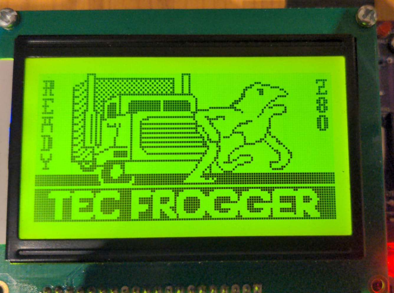
The TEC Frogger game uses the GLCD and its API routines.
GLCD API Terminal Emulator Calls
initTerminal #23 (17H)
Initialise the GLCD for terminal emulation. This routine is to be called before any TERMINAL routine is called. It will set graphics and scroll buffers. It also Clears the GBUF, sets the cursor to top left and displays the cursor. This routine will also call initLCD.
- Input: none
- Output: none
- Destroy: All
autoLF #31 (1FH)
Automatic Line Feed when the cursor reaches the end of the row. When the cursor passes the last column, character entered via the sendCharToLCD will either wrap around, or start on a new line.
- Input: C = 0, Auto LF set, C <> 0, not set
- Output: none
- Destroy: A
plotAlways #33 (21H)
When sendCharToLCD is called, determine if the character should be sent immediately to the GLCD or be held in a buffer. If held in a buffer, call plotToLCD to update the GLCD. The default is ON and characters will be sent immediately. Turning this flag OFF can speed up the output if multiple characters are sent to the screen. Once sent, characters can be plotted all at once. If displaying characters directly from a keyboard input, this flag should be set ON.
- Input: C = 0, Plot Always set, C non zero, not set
- Output: none
- Destroy: A
sendCharToLCD #24 (18H)
Send or handle ASCII characters to the GLCD screen. This routine displays ASCII characters to the GLCD screen and handles some special control characters. It also handles scrolling history of 10 lines. Characters are drawn at the current cursor position. The Cursor will increment when a character is drawn. Characters will automatically be displayed on the LCD. Some special characters are:
CR/0DHmoves the cursor down and resets its column.LF/0AHis ignored.FF/0CHclears the terminal and scroll buffer; destroysAF,BC,DE,HL.BS/08Hdeletes the character at the cursor and moves the cursor back one.HT/09Htabs 4 spaces.UP/05Hscrolls up one line if possible.DN/06Hscrolls down one line if possible.- Input:
C= ASCII character to send to the LCD screen, orC = 0to draw the cursor only - Destroy: all
ld c,65         ;ASCII 'A'
ld a,24         ;sendCharToLCD
rst 18H
ld c,0DH        ;Carriage Return
ld a,24         ;sendCharToLCD
rst 18H
sendStringToLCD #25 (19H)
Send a string of characters to the GLCD. Prints a string pointed by DE at the current cursor. It stops printing and returns when either a CR is printed or when the next byte is the same as what is in register C.
- Input:
C= character to stop printing string - Input:
DE= address of string to print - Destroy: all
ld de,text      ;Text to display
ld c,0          ;terminate on zero
ld a,25         ;sendStringToLCD
rst 18H
text: .db "Hello TEC-1G!",0
sendRegToLCD #26 (1AH)
Display a byte or register in ASCII on the GLCD at the current cursor
- Input: C = byte to convert and display
- Destroy: ALL
ld c,a          ;display register A
ld a,26         ;sendRegToLCD
rst 18H
ld c,7BH        ;display '7B'
ld a,26         ;sendRegToLCD
rst 18H
sendHLToLCD #27 (1BH)
Display the register HL in ASCII on the GLCD at the current cursor
- Input: HL = 2-byte register to convert and display
- Destroy: ALL
ld hl,0A6CH     ;display '0A6C'
ld a,27         ;sendHLToLCD
rst 18H
setCursor #28 (1CH)
Set the Graphic cursor position for Terminal Emulation. Update is ignored if either X,Y input is out of bounds.
- Input:
B= X position in pixels (0-127) - Input:
C= Y position in pixels (0-63) - Destroy:
A
ld bc,4020H     ;cursor at X=64, Y=32 (middle of screen)
ld a,28         ;setCursor
rst 18H
getCursor #29 (1DH)
Get the current cursor position
- Input: none
- Output:
B= X position in pixels (0-127) - Output:
C= Y position in pixels (0-63)
displayCursor #30 (1EH)
Turn the cursor ON or OFF. Default is Cursor ON
- Input: C = 0, Turn cursor on, C=non zero, turn cursor off
- Destroy: ALL
GLCD Examples
Provided in the TEC-1G GitHub repository are three GLCD programs. The programs have already been converted to Intel Hex files and are ready to load onto the TEC. All programs start at address 2000H. Source code for all programs are provided and can be changed and studied.
The TEC-1G GitHub account is here: TEC-1G GitHub repository and the GLCD examples are in the TEC-Deck/Graphical_LCD directory.
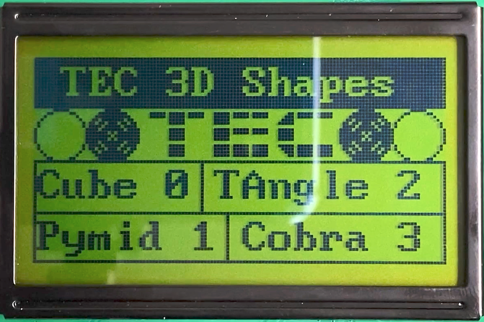
lcd_3d_demo
Draw 3D wireframe graphics and rotate them. This program requires keypad input to rotate the objects. Buttons 4,8 and C rotate the object in the 3-axis. Plus and Minus will zoom the object in and out. 0 will return to the main menu. Pressing GO will exit the program
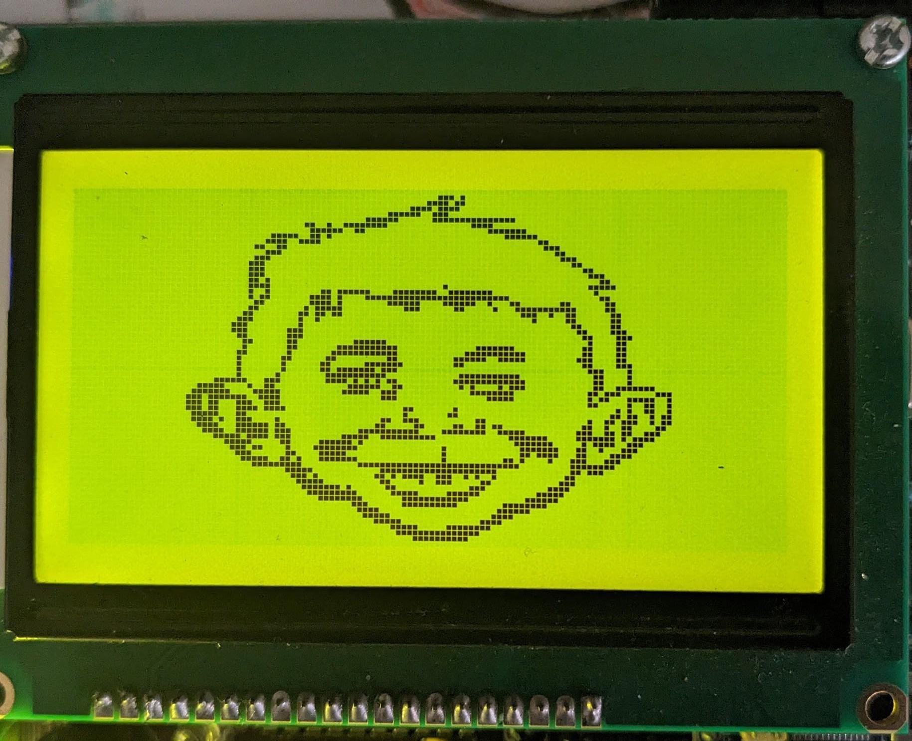
lcd_mad_program
Draw Alfred E. Neuman’s face. This program draws lines between two points and creates the face of the Mad Magazine mascot. It draws one line at a time, similar to how it would display on an Apple ][. But if the program is run at 2022H it will generate instantly. See Meat Fighter’s Mad Magazine demo notes.
lcd_maze_gen
Create a maze. This program generates a maze using a recursive backtracking algorithm. Watch the maze slowly generate before your eyes.
Some easy-to-type examples have also been provided in the Quick Start Programs chapter below.