Real Time Clock Add-On
A RTC add-on board that connects to the General Purpose IO port on the TEC-1G can be interfaced with Mon3. The board uses the DS1302 Real Time Clock chip. The RTC chip is designed to respond on port FCH.
The DS1302 supports 12 and 24 hour clock modes, a 100 year calendar (2000-2099) with leap year support, and 31 bytes of general purpose nonvolatile RAM. The TEC Designers have called the NVRAM, “Parameter RAM” or PRAM.
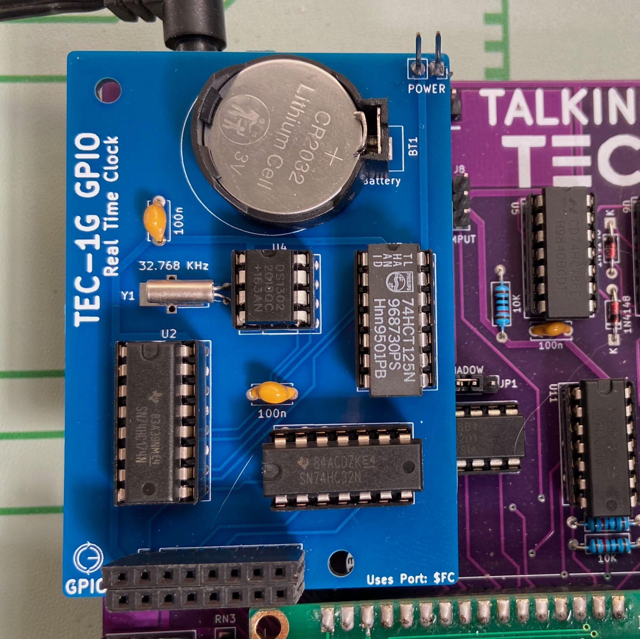
RTC add-on board connected to the TEC-1G GPIO port.
To initially set the RTC, a convenient RTC Setup routine has been provided in the Settings item in the Main Menu. Select “Configure RTC”. Press the following keys to update the time/date: 0 = Hour, 1 = Minute, 2 = Second, 3 = 12/24h, 4 = Day of week, 5 = Day, 6 = Month, 7 = Year, 8 = View RTC PRAM, F = Reset RTC, AD = Exit. When viewing RTC PRAM data, Plus = Move Down, Minus = Move Up, AD = Exit back to RTC Setup.
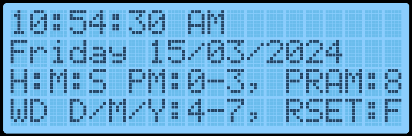
RTC setup display.
Mon3 will automatically utilise the internal PRAM to retain some settings when the TEC-1G is powered down. 14 free bytes are available to be used by the user. The reserved Mon3 PRAM slots are:
| Slot | Reserved for |
|---|---|
0-5 |
Quick Jump Addresses |
6-11 |
Start/End/Dest Addresses |
12-13 |
Baud Rate |
14-15 |
Addr. Inc. / Beep |
16-29 |
User Free RAM |
30 |
Mon3 Checksum |
When the RTC board is first used, TEC-1G settings are saved to the PRAM during power on. Manual resetting of the PRAM can also be achieved by selecting the “Reset RTC & PRAM” option in the Settings item in the Main Menu. This will reset the time/date and Mon3 reserved values.
RTC API Calls
The RTC API uses the standard RST 10H call with the addition of the B
register to specify which RTC API function is required. This way, all RTC
functions only occupy a single Mon3 API call.
General Interface
ld c,2EH       ;RTC API call number
ld b,[RTC Call Number]
rst 10H
Examples
          ;Get the current time
01 2E 02  ld bc,022EH      ;getTime + RTC API
D7        rst 10H

          ;Set the current time to 10:24:46
01 2E 03  ld bc,032EH      ;setTime + RTC API
21 00 30  ld hl,1024H      ;10 hours, 24 minutes
16 46     ld d,46H         ;46 seconds
D7        rst 10H

          ;Write a byte to the RTC NV Ram
01 2E 0C  ld bc,0C2EH      ;writeRTCbyte + RTC API
11 FF 02  ld de,02FFH      ;Save FF in position 02
D7        rst 10H
RTC Routine List
| Routine | # | 0x |
|---|---|---|
checkDS1302 |
0 | 00 |
resetDS1302 |
1 | 01 |
getTime |
2 | 02 |
setTime |
3 | 03 |
getDate |
4 | 04 |
setDate |
5 | 05 |
getDay |
6 | 06 |
setDay |
7 | 07 |
get1224Mode |
8 | 08 |
set12HrMode |
9 | 09 |
set24HrMode |
10 | 0A |
readRTCByte |
11 | 0B |
writeRTCByte |
12 | 0C |
burstRTCRead |
13 | 0D |
BCDToBin |
14 | 0E |
binToBCD |
15 | 0F |
formatTime |
16 | 10 |
formatDate |
17 | 11 |
RTCSetup |
18 | 12 |
checkDS1302 #0 (00H)
Check if a DS1302 is detectable, by verifying that the DS1302’s registers return expected results.
- Input: none
- Output:
Carry flagset = no RTC add-on board present - Destroy:
A
resetDS1302 #1 (01H)
Resets the DS1302 to a known state - clears existing Time and Calendar. Does not clear RTC RAM. Sets DS1302 to 01:00.00 AM, 01/01/2000.
- Input: none
- Destroy: none
Note: To be used only when the RTC requires a settings reset e.g. if it’s not
“ticking”. Use checkDS1302 to “reset” the DS1302 to a ready state, as part of
program initialization.
getTime #2 (02H)
Get time from RTC. Time is formatted in either 12 or 24 hour mode, depending on selected mode.
- Input: none
- Output:
H= hour, bit 5=am/pm flag (in 12hr mode). 1=PM - Output:
L= minute - Output:
D= second - Destroy:
A
Note that all returned registers are BCD coded, so 10:24:36 results in
HL = 1024h, D = 36h.
setTime #3 (03H)
Sets the time in the RTC chip. Time is formatted in either 12 or 24 hour mode, depending on selected mode.
- Input:
H= hour, bit 5=am/pm flag (in 12hr mode). 1=PM - Input:
L= minute - Input:
D= second - Destroy:
A,E
The 12/24 hour mode flag is preserved. Note that all registers are BCD
coded, so 10:24:36 is formatted as HL = 1024h, D = 36h.
getDate #4 (04H)
Returns the present Calendar date, month, year.
- Input: none
- Output:
H= date - Output:
L= month - Output:
DE= year - Destroy:
A
Note that values returned are BCD coded.
setDate #5 (05H)
Sets the Calendar to a specified date/month/year. Invalid dates may be accepted e.g. 30 February as the DS1302 does not validate dates as programmed; it simply rolls over at midnight.
- Input:
H= date - Input:
L= month - Input:
DE= year 2000-2099,Dis assumed to be20h - Destroy:
A
Note that values returned are BCD coded.
getDay #6 (06H)
Gets the Day of the week i.e. “Monday”, “Tuesday”, etc. 01 = Monday, 07 = Sunday.
- Input: none
- Output:
D= 01-07 (Day of week) - Output:
HL= address of zero terminated DOW string - Destroy:
A
The names of the days of the week are stored in the Mon3 ROM; HL points to the correct string for that day.
setDay #7 (07H)
Sets the Day of the week. 01 = Monday, 07 = Sunday.
- Input:
D= 01-07 (Day of week) - Output:
Carry Flagset = invalid value supplied - Destroy:
A
get1224Mode #8 (08H)
Reports if the RTC is currently in 12 or 24 hour mode.
- Input: none
- Output:
A= 00H (24hr), 80H (12hr),Zero flagset - Destroy: none
set12HrMode #9 (09H)
Set RTC to 12 hour mode. That is, the hour is subsequently returned as 01-12, and an AM/PM flag.
- Input: none
- Output:
Carry Flagset = already in 12 hr mode - Destroy:
A,D
set24HrMode #10 (0AH)
Set RTC to 24 hour mode (also known as Military Time). That is, the hour is subsequently returned as 00-23.
- Input: none
- Output:
Carry Flagset = already in 24 hr mode - Destroy:
A,D
readRTCByte #11 (0BH)
Reads a byte from the RTC PRAM.
- Input:
D= memory slot to return 0-30 - Output:
A= value stored in memory - Destroy: none
writeRTCByte #12 (0CH)
Writes a byte to the RTC PRAM.
- Input:
D= memory slot to write to 0-30 - Input:
E= value to store - Destroy:
A
burstRTCRead #13 (0DH)
Reads all 31 RTC PRAM bytes and fills a user-supplied buffer with that data. The user buffer should be 31 bytes long.
- Input:
HL= location to write to (31 bytes) - Output:
HL= moved to address after last byte - Destroy:
A
BCDToBin #14 (0EH)
Converts the value in register A from BCD encoded, to binary. i.e. 23h
becomes 23 decimal.
- Input:
A= BCD Value to convert - Output:
A= Binary value of BCD - Destroy: none
binToBCD #15 (0FH)
Converts the value in register A from binary to BCD. i.e. 52 decimal
becomes 52h.
- Input:
A= Binary Value to convert - Output:
A= BCD value of Binary - Destroy: none
formatTime #16 (10H)
Takes a time and fills a user-supplied buffer with an ASCIIZ string formatted as human-readable text. The user-supplied buffer should be at least 12 bytes long.
Bits 7 and 5 of the hour is used to format the time, if it is a 12hr mode timestamp - AM or PM is appended accordingly.
- Input:
H= hour (bit 7 = 12/24hr, 1=12hr mode; bit 5 = am/pm flag, 1=PM) - Input:
L= minute - Input:
D= second - Input:
IY= address of user supplied buffer - Output:
IY= moved to address after last byte - Destroy:
A
formatDate #17 (11H)
Takes a date and fills a user-supplied buffer with an ASCIIZ string formatted as human-readable text. The user-supplied buffer should be at least 11 bytes long. Dates are output as DD/MM/YYYY
- Input:
H= date - Input:
L= month - Input:
DE= year (2000-2099) - Input:
IY= address of user supplied buffer - Output:
IY= moved to address after last byte - Destroy:
A
RTCSetup #18 (12H)
Standalone application that assists with configuring the RTC for initial use. The LCD displays the current RTC time and date with the instructions.
Keys: 0 = Hour, 1 = Minute, 2 = Second, 3 = 12/24h, 4 = Day of week, 5 = Day, 6 = Month, 7 = Year, 8 = View RTC PRAM, F = Reset RTC, AD = Exit.
When viewing RTC RAM data, Plus = Move Down, Minus = Move Up, AD = Exit back to RTC Setup.
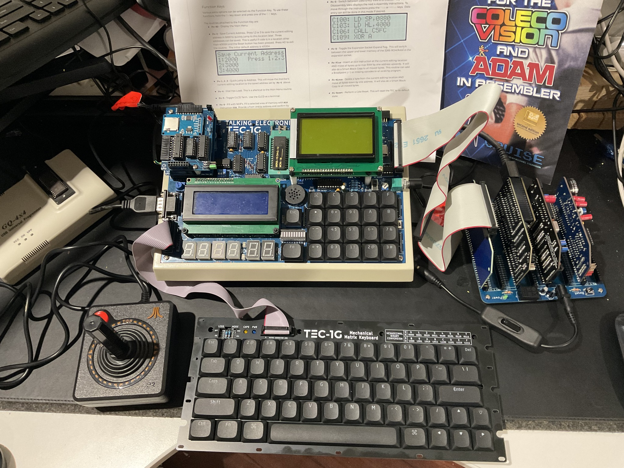
A TEC-1G with various add-on boards. Credit: Andrew McRae.